
Page 111 - Solar Power in Building Design The Engineer's Complete Design Resource
P. 111
ROOF-MOUNT INSTALLATIONS 81
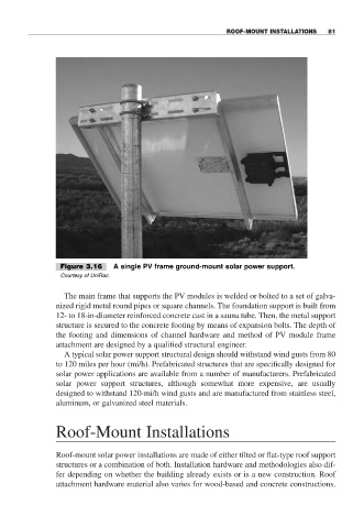
Figure 3.16 A single PV frame ground-mount solar power support.
Courtesy of UniRac.
The main frame that supports the PV modules is welded or bolted to a set of galva-
nized rigid metal round pipes or square channels. The foundation support is built from
12- to 18-in-diameter reinforced concrete cast in a sauna tube. Then, the metal support
structure is secured to the concrete footing by means of expansion bolts. The depth of
the footing and dimensions of channel hardware and method of PV module frame
attachment are designed by a qualified structural engineer.
A typical solar power support structural design should withstand wind gusts from 80
to 120 miles per hour (mi/h). Prefabricated structures that are specifically designed for
solar power applications are available from a number of manufacturers. Prefabricated
solar power support structures, although somewhat more expensive, are usually
designed to withstand 120-mi/h wind gusts and are manufactured from stainless steel,
aluminum, or galvanized steel materials.
Roof-Mount Installations
Roof-mount solar power installations are made of either tilted or flat-type roof support
structures or a combination of both. Installation hardware and methodologies also dif-
fer depending on whether the building already exists or is a new construction. Roof
attachment hardware material also varies for wood-based and concrete constructions.