
Page 114 - Solar Power in Building Design The Engineer's Complete Design Resource
P. 114
84 SOLAR POWER SYSTEM DESIGN CONSIDERATIONS
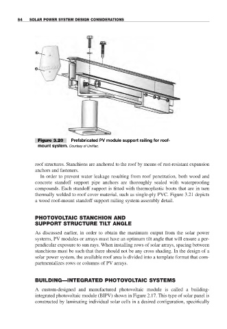
Figure 3.20 Prefabricated PV module support railing for roof-
mount system. Courtesy of UniRac.
roof structures. Stanchions are anchored to the roof by means of rust-resistant expansion
anchors and fasteners.
In order to prevent water leakage resulting from roof penetration, both wood and
concrete standoff support pipe anchors are thoroughly sealed with waterproofing
compounds. Each standoff support is fitted with thermoplastic boots that are in turn
thermally welded to roof cover material, such as single-ply PVC. Figure 3.21 depicts
a wood roof-mount standoff support railing system assembly detail.
PHOTOVOLTAIC STANCHION AND
SUPPORT STRUCTURE TILT ANGLE
As discussed earlier, in order to obtain the maximum output from the solar power
systems, PV modules or arrays must have an optimum tilt angle that will ensure a per-
pendicular exposure to sun rays. When installing rows of solar arrays, spacing between
stanchions must be such that there should not be any cross shading. In the design of a
solar power system, the available roof area is divided into a template format that com-
partmentalizes rows or columns of PV arrays.
BUILDING—INTEGRATED PHOTOVOLTAIC SYSTEMS
A custom-designed and manufactured photovoltaic module is called a building-
integrated photovoltaic module (BIPV) shown in Figure 2.17. This type of solar panel is
constructed by laminating individual solar cells in a desired configuration, specifically