
Page 225 - Standard Handbook Petroleum Natural Gas Engineering VOLUME2
P. 225
194 Reservoir Engineering
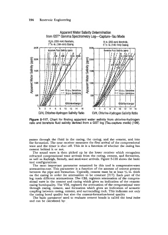
Apparent Water Salinity Determination
from GSF Gamma Spectrometry Log-Capture-Tau Mode
10-in. (255-mm) Borehole, 8-in. (203-mm) Borehole,
7 5/8-in. (194-mm) Casing 5'/2-in. (Ia-rnrn) Casing
- 32-p.u. Sandstone
- - 16-p.u. Sandstone
TTl-
-
C3Schlumberger
2 4 6 8 10 12 14 16 0 4 6 8 10 12 14 i
CVH, Chlorine-Hydrogen Salinity Ratio CVH, Chlorine-Hydrogen Salinity Ratio
Flgure 5-117. Chart for finding apparent water salinity from chlorine-hydrogen
ratio and borehole fluid salinity derived from a GST log (Tau-capture mode) [199].
passes through the fluid in the casing, the casing, and the cement, and into
the formation. The near receiver measures the first arrival of the compressional
wave and the timer is shut off. This At is a function of whether the casing has
cement behind it or not.
The sound wave is then picked up by the lower receiver which recognizes
refracted compressional wave arrivals from the casing, cement, and formation,
as well as Rayleigh, Stonely, and mud-wave arrivals. Figure 5-118 shows the basic
tool configurations.
The most important parameter measured by this tool is compressive-wave
attenuation-rate. This parameter is a function of the amount of cement present
between the pipe and formation. Typically, cement must be at least in. thick
on the casing in order for attenuation to be constant [217]. Each part of the
log reads different attenuations. The CBL registers attenuation of the compres-
sional wave in the cement and casing which gives an indication of the cement-
casing bondquality. The VDL registers the attenuation of the compressional wave
through casing, cement, and formation which gives an indication of acoustic
coupling between casing, cement, and surrounding rock. This indicates not only
the casing bond quality but also the cement-formation-bond quality
The basic parameter used to evaluate cement bonds is called the bond in&x
and can be calculated by: