Page 479 - Standard Handbook Petroleum Natural Gas Engineering VOLUME2
P. 479
Flow  of  Fluids   435


                 presented flow-pattern and flow-regime maps in which various areas are indicated
                 on  a  graph  for which  there  are  two  independent  coordinates. Maps  are also
                 dependent  on  ranges  of  pipe  inclination  from  vertical  upward  to  vertical
                 downward [19]. Selection of  the appropriate flow regime map is based solely
                 on the pipe segment inclincation 8 from the horizontal, as shown below:


                 Range of lnclinatlon from the Horizontal              Regime Maps

                 e = 900  to 150                                       Upward inclined
                 e = 150 to-io0                                        Near horizontal
                 e = -1 00  to -900                                    Downward inclined

                 Flow Regimes

                   The steps in the determination of  the flow regime are as follows:
                   1. Calculate dimensionless parameters.
                   2.  Refer to flow regime maps laid out in coordinates of  these parameters.
                   3.  Determine the  flow regime by  locating the  operating point on  the flow
                      regime map.
                   The  discussions in  the  following sections treat  the  flow regime maps  for
                 vertical  upward  (e  =  90"); slightly inclined  (0 =  15" to  -10") and  vertical
                 downward inclinations.
                   To proceed with the calculations of the flow regime, it is necessary to calculate
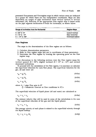
                 the superficial velocities for each flow phase. The superficial velocities for the
                 gas, oil and water are

                                                                               (6-65~)

                                                                               (6-653)
                   v,   = qPp                                                  (6-65c)

                 where A,  = pipe flow area in ft2
                        q = volumetric flowrate at flow conditions in ft3/s

                 The superficial velocities of  liquid phase (oil and water) are calculated as
                                                                               (6-65d)

                 The mixture velocity that will  be used in some of  the calculations is  the sum
                 of  the superficial velocities of the gas and the liquid phases:
                                                                               (6-65e)

                 The average velocity of each phase is related to the superficial velocity through
                 the liquid holdup:
                   U,  = vL = vsJHL                                            (6-658

