
Page 22 - Steam Turbines--Design, Applications, and Rerating by Heinz-Bloch, Murari-Singh
P. 22
Introduction 3
diaphragms in a turbine are designed to direct the steam flow into
well-formed, high-speed jets as the steam expands from inlet to
exhaust pressure. These jets strike moving rows of blades mounted on
the rotor. The blades convert the kinetic energy of the steam into rota-
tion energy of the shaft.
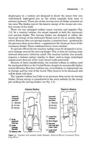
There are two principal turbine types: reaction and impulse (Fig.
1.2). In a reaction turbine, the steam expands in both the stationary
and moving blades. The moving blades are designed to utilize the
steam jet energy of the stationary blades and to act as nozzles them-
selves. Because they are moving nozzles, a reaction force—produced by
the pressure drop across them—supplements the steam jet force of the
stationary blades. These combined forces cause rotation.
To operate efficiently the reaction turbine must be designed to mini-
mize leakage around the moving blades. This is done by making most
internal clearances relatively small. The reaction turbine also usually
requires a balance piston (similar to those used in large centrifugal
compressors) because of the large thrust loads generated.
Because of these considerations, the reaction turbine is seldom used
for mechanical drive in the United States, despite its occasionally higher
initial efficiency. Reaction turbines are, nevertheless, in widespread use
in Europe and the rest of the world. They deserve to be discussed and
will be dealt with later.
The impulse turbine has little or no pressure drop across its moving
blades. Steam energy is transferred to the rotor entirely by the steam
jets striking the moving blades (see Fig. 1.3).
Figure 1.2 Impulse and reaction blade features. (General Electric Company, Fitch-
burg, Mass.)