
Page 34 - Steam Turbines--Design, Applications, and Rerating by Heinz-Bloch, Murari-Singh
P. 34
Introduction 15
(a)
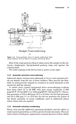
Figure 1.14 Cross-sectional views of typical mechanical drive
steam turbines. (General Electric Company, Fitchburg, Mass.)
Most of the stage pressure drop is taken across the nozzles in the sta-
tionary diaphragms. Spring-backed packing rings seal against the
rotating shaft.
The solid coupling to the driven load is shown to the right.
1.3.2 Automatic extraction noncondensing
Industrial plants having steam demands at two or more pressure lev-
els can benefit from the use of these turbines. They provide the flexi-
bility to automatically respond to variations in steam demands at the
extraction and the exhaust.
In recent years, typical mechanical drive noncondensing turbines
have been rated 10 to 40 MW with inlet steam conditions of 600
psig/750°F (41 bar/400°C) to 1450 psig/950°F (100 bar/510°C). Extrac-
tion pressures of 150 to 650 psig (10.3 to 13.8 bar) for the high pressure
and 25 to 200 psig (1.7 to 13.8 bar) for the low pressure are typical of
the broad spectrum of steam conditions used in industrial plants
where these units are applied.
1.3.3 Automatic extraction condensing
These units provide additional operating flexibility and the ability to
control power generation, as well as process header pressures.They are
well suited to third-party cogeneration systems because of their ability