
Page 54 - Steam Turbines--Design, Applications, and Rerating by Heinz-Bloch, Murari-Singh
P. 54
Turbine Casing and Major Stationary Components 35
valves while leaving the second one in operation. This could be an
important reliability assurance task.
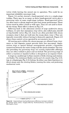
Figure 1.6, earlier, showed a hand-operated valve in a single-stage
turbine. There may be as many as three hand-operated valves plus a
governing valve in some single-stage turbines. Hand-operated valves
are often used to obtain improved part load steam performance. These
valves must be either closed or wide open. They are not used to throt-
tle the steam. Their effect is shown in Fig. 2.8.
Referring back to the admission section of large multivalve steam
turbines, we note that emergency stop valves, also called main shutoff
or trip-throttle valves (Fig. 2.9, item 2) are often provided with steam
strainers, item 5, that are built into the steam chest, item 1. They are
typically removable without having to dismantle pipework. Figure 2.9
shows these control valves operated by servomotors, item 12.
All moving parts within the steam passage are allowed large clear-
ances so that deposits cannot prevent their free movement. Angle-
section rings or special linkage arrangements provide a kinematic
connection between the outer casing and the steam chamber. The noz-
zles preceding the governing stage are usually replaceable although
they are often welded in place and not bolted. The governing stage of
either a reaction or impulse turbine is designed as an impulse wheel.
A stage in a multistage turbine consists of both rotating and station-
ary blades. The stationary blades can be part of a nozzle ring, Fig. 2.10,
top, or a diaphragm, Fig. 2.10, bottom. In either case their function is to
direct steam onto the rotating blades, turning the rotor, and producing
mechanical work.
Figure 2.8 Improved part load performance (efficiency increase) achieved
by closing hand valves. (Coppus-Murray Turbomachinery Corporation,
Burlington, Iowa)