
Page 142 - Steam Turbines Design, Applications, and Rerating
P. 142
Turbine Blade Design Overview 123
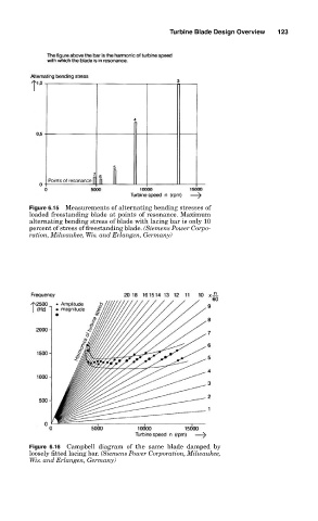
Figure 6.15 Measurements of alternating bending stresses of
loaded freestanding blade at points of resonance. Maximum
alternating bending stress of blade with lacing bar is only 10
percent of stress of freestanding blade. (Siemens Power Corpo-
ration, Milwaukee, Wis. and Erlangen, Germany)
Figure 6.16 Campbell diagram of the same blade damped by
loosely fitted lacing bar. (Siemens Power Corporation, Milwaukee,
Wis. and Erlangen, Germany)