
Page 137 - Steam Turbines Design, Applications, and Rerating
P. 137
118 Chapter Six
excitation forces and resonance conditions are not dangerous as long as
the damping is high. So much of the vibration energy is transformed
into heat that the vibration amplitude remains small.
The vibration of a blade is damped by the material-damping capac-
ity, by the damping at the blade root and by the steam surrounding the
blade. All cylindrical blades on drum rotors from such notable manu-
facturers as Siemens are machined with integral shrouds. When the
blades of a row are assembled, these shrouds are pressed against each
other and form a closed shroud ring (Fig. 6.10).
The complete shroudband links all blades of the stage to a coupled
vibration system whose natural frequencies are substantially higher
than those experienced by individual freestanding blades.
The transmitted energy of a vibration excitation into the linked blade
system will be equally distributed to all blades within a row; the entire
blade row has to be excited. For comparison, in an unlinked system
(freestanding blades) the excitation energy will mainly be absorbed by
the blade that has a natural frequency equal to the excitation fre-
quency. This blade is then susceptible to breakage.
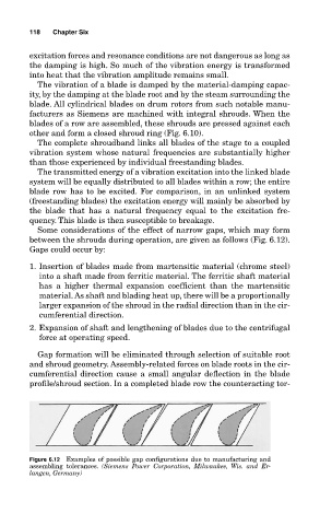
Some considerations of the effect of narrow gaps, which may form
between the shrouds during operation, are given as follows (Fig. 6.12).
Gaps could occur by:
1. Insertion of blades made from martensitic material (chrome steel)
into a shaft made from ferritic material. The ferritic shaft material
has a higher thermal expansion coefficient than the martensitic
material. As shaft and blading heat up, there will be a proportionally
larger expansion of the shroud in the radial direction than in the cir-
cumferential direction.
2. Expansion of shaft and lengthening of blades due to the centrifugal
force at operating speed.
Gap formation will be eliminated through selection of suitable root
and shroud geometry. Assembly-related forces on blade roots in the cir-
cumferential direction cause a small angular deflection in the blade
profile/shroud section. In a completed blade row the counteracting tor-
Figure 6.12 Examples of possible gap configurations due to manufacturing and
assembling tolerances. (Siemens Power Corporation, Milwaukee, Wis. and Er-
langen, Germany)