
Page 134 - Steam Turbines Design, Applications, and Rerating
P. 134
Turbine Blade Design Overview 115
The final blade of each row is identical with the normal blades except
for the missing recesses in the T-root. The final blade is always secured
with high-strength fasteners. Thus the spacing of the final blade does
not differ from that of the normal blades.
The inserted, nonshrouded, freestanding blade has been largely dis-
continued in industrial turbine construction.
Guide blades and rotor blades typically have an identical blade pro-
file. This profile is geometrically enlarged by a constant factor so that a
range of geometrically similar blade profiles is created. For all profile
sizes the optimal pitch ratio (pitch/profile chord length) is selected. The
stagger angles of the blade profiles are graded and are equal for all pro-
file sizes. In essence, geometrically similar blade cascades are thus cre-
ated for all profile sizes.
The profile chord length remains constant for the full blade length.
Only a few standardized stagger angles are generally used by a given
manufacturer. The ratio of blade length to mean blade diameter is typ-
ically limited to 0.2. Therefore the pitch at hub and blade tip cannot
deviate too much from the optimal value. At the same time the fan
losses stay within a reasonable range.
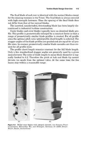
(a) (b)
Figure 6.9 Milled rotor blades with integral shrouds. ((a) Siemens Power
Corporation, Milwaukee, Wis. and Erlangen, Germany (b) ASEA Brown-
Boveri, Baden, Switzerland)