
Page 131 - Steam Turbines Design, Applications, and Rerating
P. 131
112 Chapter Six
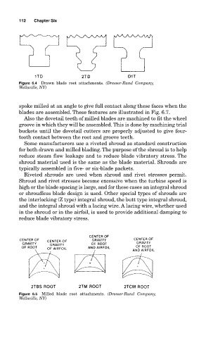
Figure 6.4 Drawn blade root attachments. (Dresser-Rand Company,
Wellsville, NY)
spoke milled at an angle to give full contact along these faces when the
blades are assembled. These features are illustrated in Fig. 6.7.
Also the dovetail teeth of milled blades are machined to fit the wheel
groove in which they will be assembled. This is done by machining trial
buckets until the dovetail cutters are properly adjusted to give four-
tooth contact between the root and groove teeth.
Some manufacturers use a riveted shroud as standard construction
for both drawn and milled blading. The purpose of the shroud is to help
reduce steam flow leakage and to reduce blade vibratory stress. The
shroud material used is the same as the blade material. Shrouds are
typically assembled in five- or six-blade packets.
Riveted shrouds are used when shroud and rivet stresses permit.
Shroud and rivet stresses become excessive when the turbine speed is
high or the blade spacing is large, and for these cases an integral shroud
or shroudless blade design is used. Other special types of shrouds are
the interlocking (Z type) integral shroud, the butt type integral shroud,
and the integral shroud with a lacing wire. A lacing wire, whether used
in the shroud or in the airfoil, is used to provide additional damping to
reduce blade vibratory stress.
Figure 6.5 Milled blade root attachments. (Dresser-Rand Company,
Wellsville, NY)