
Page 136 - Steam Turbines Design, Applications, and Rerating
P. 136
Turbine Blade Design Overview 117
Blade roots and shrouds are sometimes designed in rhomboid shape.
The rhomboid faces are ground and thus provide an optimal fit for the
blade roots and blade shrouds.
Some notes on the stresses acting on the turbine blading will be of
interest. The turbine blading is subject to dynamic forces because the
steam flow entering the rotor blades in the circumferential direction is
not homogeneous. Blades alternate with flow passages so that the rotat-
ing blades pass areas of differing flow velocities and directions. Since
the forces affecting the rotor blading are generated by this flow, the
blade stresses also vary. The magnitude of the stress variation depends
very much on the quality of the blading. Poorly designed blading will
often experience flow separation. This induces particularly high bend-
ing stresses on the blades. Dynamic blade stresses are also produced by
ribs or other asymmetries in the flow area.
If the steam turbine is driving a compressor, surge events can induce
high dynamic stresses in the rotor blades. These surges excite torsional
vibrations of the turbine rotor which in turn excite bending oscillations
in the blades. The severity of the alternating bending load in the blade
due to the dynamic blade stresses depends on such parameters as mag-
nitude of the dynamic blade force, frequency level of the blade, and the
damping properties of the blade.
The frequency level is determined by the ratio of natural frequency
to exciting frequency. With constant dynamic blade force the vibra-
tional amplitude and thus the bending load increase with the decreas-
ing difference of these two frequencies (resonance conditions).
With a given dynamic blade force and a given resonance condition
the alternating bending stress is determined by the damping. Large
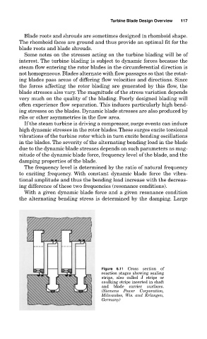
Figure 6.11 Cross section of
reaction stages showing sealing
strips, also called J strips or
caulking strips inserted in shaft
and blade carrier surfaces.
(Siemens Power Corporation,
Milwaukee, Wis. and Erlangen,
Germany)