
Page 151 - Steam Turbines Design, Applications, and Rerating
P. 151
132 Chapter Seven
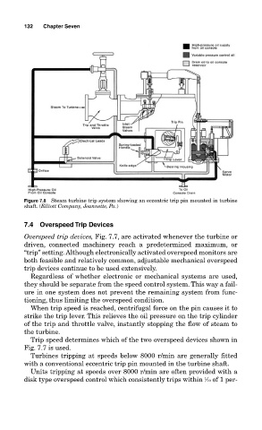
Figure 7.8 Steam turbine trip system showing an eccentric trip pin mounted in turbine
shaft. (Elliott Company, Jeannette, Pa.)
7.4 Overspeed Trip Devices
Overspeed trip devices, Fig. 7.7, are activated whenever the turbine or
driven, connected machinery reach a predetermined maximum, or
“trip” setting. Although electronically activated overspeed monitors are
both feasible and relatively common, adjustable mechanical overspeed
trip devices continue to be used extensively.
Regardless of whether electronic or mechanical systems are used,
they should be separate from the speed control system. This way a fail-
ure in one system does not prevent the remaining system from func-
tioning, thus limiting the overspeed condition.
When trip speed is reached, centrifugal force on the pin causes it to
strike the trip lever. This relieves the oil pressure on the trip cylinder
of the trip and throttle valve, instantly stopping the flow of steam to
the turbine.
Trip speed determines which of the two overspeed devices shown in
Fig. 7.7 is used.
Turbines tripping at speeds below 8000 r/min are generally fitted
with a conventional eccentric trip pin mounted in the turbine shaft.
Units tripping at speeds over 8000 r/min are often provided with a
1
disk type overspeed control which consistently trips within ⁄10 of 1 per-