
Page 152 - Steam Turbines Design, Applications, and Rerating
P. 152
Turbine Auxiliaries 133
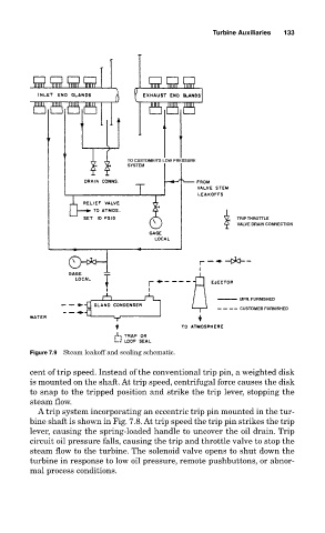
Figure 7.9 Steam leakoff and sealing schematic.
cent of trip speed. Instead of the conventional trip pin, a weighted disk
is mounted on the shaft. At trip speed, centrifugal force causes the disk
to snap to the tripped position and strike the trip lever, stopping the
steam flow.
A trip system incorporating an eccentric trip pin mounted in the tur-
bine shaft is shown in Fig. 7.8. At trip speed the trip pin strikes the trip
lever, causing the spring-loaded handle to uncover the oil drain. Trip
circuit oil pressure falls, causing the trip and throttle valve to stop the
steam flow to the turbine. The solenoid valve opens to shut down the
turbine in response to low oil pressure, remote pushbuttons, or abnor-
mal process conditions.