
Page 207 - Steam Turbines Design, Applications, and Rerating
P. 207
186 Chapter Ten
bucket cover. Of the two, the labyrinth seals in the high-pressure end of
the machine have the potential of generating the greatest destabilizing
force. While rotor instabilities from bearing oil whirl are well known,
instabilities from labyrinth and spill strip seals are understood to a
lesser degree.
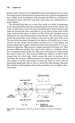
The destabilizing force on a rotor from seals is a direct consequence
of the frictional drag from the circumferential swirl of the steam. If a
rotor is centered in a seal, the local circumferential swirl velocity is the
same all around the rotor, and there is no net force on the rotor. If the
rotor is moved off center, as shown in Fig. 10.13, the chamber area is
reduced at the top and increased on the bottom. The reduction in area
at the top causes the swirl velocity to increase in that part of the seal.
The area that has been enlarged at the bottom will locally have a lower
velocity. As the steam travels from location A to C in the figure, the
steam experiences a higher drag force than from going from C to A in a
clockwise direction. This induces a higher pressure at A than at C. This
pressure difference pushes the rotor to the right in a clockwise direc-
tion around the center of the seal. The rotor now begins to whirl around
the center of the seal. The pressure difference between A and C feeds
energy into the whirl orbit, which causes the orbit to increase. As it
increases, the pressure difference gets even larger because the reduced
area region is further decreased, causing the shaft to whirl with an
increasing amplitude. This is what is meant by self-exciting vibration.
The vibration itself produces forces that push the rotor to higher vibra-
tion levels.
Figure 10.13 Aerodynamic seal forces. (General Electric Company, Fitchburg,
Mass.)