
Page 211 - Steam Turbines Design, Applications, and Rerating
P. 211
190 Chapter Eleven
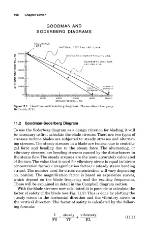
Figure 11.1 Goodman and Soderberg diagrams. (Dresser-Rand Company,
Wellsville, N.Y.)
11.2 Goodman-Soderberg Diagram
To use the Soderberg diagram as a design criterion for blading, it will
be necessary to first calculate the blade stresses. There are two types of
stresses turbine blades are subjected to: steady stresses and alternat-
ing stresses. The steady stresses in a blade are tension due to centrifu-
gal force and bending due to the steam force. The alternating, or
vibratory stresses, are bending stresses caused by the disturbances in
the steam flow. The steady stresses are the more accurately calculated
of the two. The value that is used for vibratory stress is equal to (stress
concentration factor) × (magnification factor) × (steady steam bending
stress). The number used for stress concentration will vary depending
on location. The magnification factor is based on experience curves,
which depend on the blade frequency and the exciting frequencies.
These will be explained in detail in the Campbell diagram section.
With the blade stresses now calculated, it is possible to calculate the
factor of safety of the blade (see Fig. 11.2). This is done by plotting the
steady stress in the horizontal direction and the vibratory stress in
the vertical direction. The factor of safety is calculated by the follow-
ing formula:
1 steady vibratory
= + (11.1)
FS YP EL