
Page 212 - Steam Turbines Design, Applications, and Rerating
P. 212
Campbell, Goodman, and SAFE Diagrams for Steam Turbine Blades 191
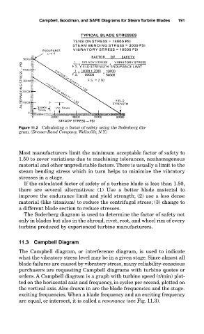
Figure 11.2 Calculating a factor of safety using the Soderberg dia-
gram. (Dresser-Rand Company, Wellsville, N.Y.)
Most manufacturers limit the minimum acceptable factor of safety to
1.50 to cover variations due to machining tolerances, nonhomogenous
material and other unpredictable factors. There is usually a limit to the
steam bending stress which in turn helps to minimize the vibratory
stresses in a stage.
If the calculated factor of safety of a turbine blade is less than 1.50,
there are several alternatives: (1) Use a better blade material to
improve the endurance limit and yield strength; (2) use a less dense
material (like titanium) to reduce the centrifugal stress; (3) change to
a different blade section to reduce stresses.
The Soderberg diagram is used to determine the factor of safety not
only in blades but also in the shroud, rivet, root, and wheel rim of every
turbine produced by experienced turbine manufacturers.
11.3 Campbell Diagram
The Campbell diagram, or interference diagram, is used to indicate
what the vibratory stress level may be in a given stage. Since almost all
blade failures are caused by vibratory stress, many reliability-conscious
purchasers are requesting Campbell diagrams with turbine quotes or
orders. A Campbell diagram is a graph with turbine speed (r/min) plot-
ted on the horizontal axis and frequency, in cycles per second, plotted on
the vertical axis. Also drawn in are the blade frequencies and the stage-
exciting frequencies. When a blade frequency and an exciting frequency
are equal, or intersect, it is called a resonance (see Fig. 11.3).