
Page 216 - Steam Turbines Design, Applications, and Rerating
P. 216
Campbell, Goodman, and SAFE Diagrams for Steam Turbine Blades 195
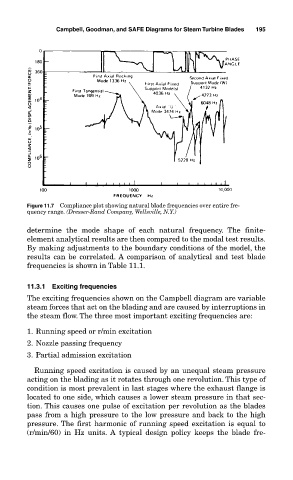
Figure 11.7 Compliance plot showing natural blade frequencies over entire fre-
quency range. (Dresser-Rand Company, Wellsville, N.Y.)
determine the mode shape of each natural frequency. The finite-
element analytical results are then compared to the modal test results.
By making adjustments to the boundary conditions of the model, the
results can be correlated. A comparison of analytical and test blade
frequencies is shown in Table 11.1.
11.3.1 Exciting frequencies
The exciting frequencies shown on the Campbell diagram are variable
steam forces that act on the blading and are caused by interruptions in
the steam flow. The three most important exciting frequencies are:
1. Running speed or r/min excitation
2. Nozzle passing frequency
3. Partial admission excitation
Running speed excitation is caused by an unequal steam pressure
acting on the blading as it rotates through one revolution. This type of
condition is most prevalent in last stages where the exhaust flange is
located to one side, which causes a lower steam pressure in that sec-
tion. This causes one pulse of excitation per revolution as the blades
pass from a high pressure to the low pressure and back to the high
pressure. The first harmonic of running speed excitation is equal to
(r/min/60) in Hz units. A typical design policy keeps the blade fre-