
Page 220 - Steam Turbines Design, Applications, and Rerating
P. 220
Campbell, Goodman, and SAFE Diagrams for Steam Turbine Blades 199
displacements of different points of the structure. For a circular sym-
metric system (e.g., bladed disk), there are points that remain station-
ary in the vibration cycle. These points fall either on a diametral line(s)
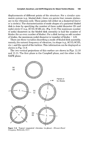
or a circle(s). The characterization of mode shapes of a packeted bladed
disk is done by specifying the number of these nodal diameter (D) and
nodal circle (C) e.g., 0C1D, 0C2D, etc. (Fig. 11.8). The maximum number
of nodal diameters in the bladed disk assembly is half the number of
blades (for an even number of blades). For a disk having an odd number
of blades, the maximum nodal diameter is (number of blades 1)/2.
There are three variables describing a mode of bladed disk assembly,
namely, the natural frequency of vibration, its shape (e.g., 0C1D, 0C3D,
etc.), and the speed of the turbine. This information can be displayed as
shown in Fig. 11.9.
The two vertical projections of this surface are shown in Figs. 11.10
and 11.11. The first plane is the Campbell plane, and the other is the
SAFE plane.
Figure 11.8 Typical tangential vibration (in-phase). (Dresser-Rand
Company, Wellsville, N.Y.)