
Page 213 - Steam Turbines Design, Applications, and Rerating
P. 213
192 Chapter Eleven
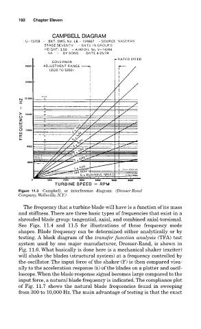
Figure 11.3 Campbell, or interference diagram. (Dresser-Rand
Company, Wellsville, N.Y.)
The frequency that a turbine blade will have is a function of its mass
and stiffness. There are three basic types of frequencies that exist in a
shrouded blade group: tangential, axial, and combined axial-torsional.
See Figs. 11.4 and 11.5 for illustrations of these frequency mode
shapes. Blade frequency can be determined either analytically or by
testing. A block diagram of the transfer function analysis (TFA) test
system used by one major manufacturer, Dresser-Rand, is shown in
Fig. 11.6. What basically is done here is a mechanical shaker (exciter)
will shake the blades (structural system) at a frequency controlled by
the oscillator. The input force of the shaker (F) is then compared visu-
ally to the acceleration response (¨ x) of the blades on a plotter and oscil-
loscope. When the blade response signal becomes large compared to the
input force, a natural blade frequency is indicated. The compliance plot
of Fig. 11.7 shows the natural blade frequencies found in sweeping
from 300 to 10,000 Hz. The main advantage of testing is that the exact