
Page 232 - Steam Turbines Design, Applications, and Rerating
P. 232
Campbell, Goodman, and SAFE Diagrams for Steam Turbine Blades 211
packets, the maximum horizontal and vertical designations will be N/2
(or (N − 1)/2 when N is odd). The diagrams are constructed by drawing
± 45° lines emanating from each integer multiple of n as shown in Figs.
11.24 and 11.25.
There are two important facts revealed by this diagram: (1) When
the 45° lines cross each other and have the same horizontal and verti-
cal designation, that mode will split, i.e., will have the same mode
designation but have two different frequencies, and (2) they also indi-
cate the harmonic contents of any mode. For a completely shrouded
arrangement, each mode contains only one harmonic, but the example
for 8 packets, the 15-nodal diameter mode has 17, 15, 9, 7, and 1 har-
monics contents as shown in Fig. 11.23.
Implications of this are that the 15-nodal diameter mode of the above
example will also respond to the 17th, 9th, 7th, and 1st harmonics of
exciting force, but with different magnitude.
11.7 Interference Diagram beyond N/2 Limit
The maximum number of mode shapes (number of nodal diameters)
plotted on an interference diagram for N blades on the disk is N/2 (or
(N − 1)/2, when N is odd). When the excitation is of higher harmonics
than N/2, two questions arise:
1. Will the higher order harmonic(s) of a force excite modes of lower
harmonic(s) content?
2. If the answer is Yes, then how can this information be depicted on
the SAFE diagram?
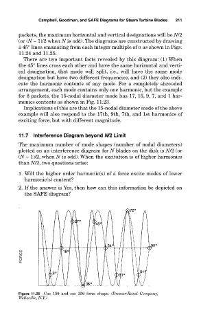
Figure 11.26 Cos 15θ and cos 25θ force shape. (Dresser-Rand Company,
Wellsville, N.Y.)