
Page 233 - Steam Turbines Design, Applications, and Rerating
P. 233
212 Chapter Eleven
For the 40-bladed disk, the maximum nodal diameter depicted on the
SAFE Diagram is 20. A force having a 15-nodal diameter shape will
excite the 15-nodal diameter mode if the frequency is equal to the nat-
ural frequency of this mode.
In Fig. 11.26, two cosine waves are plotted between 0 and 90°. They
are cosine 15θ and cosine 25θ. They intersect each other at 10 points
marked with asterisks. In 360° arc, they will intersect at 40 points. The
spacing between consecutive intersections is equal and, in turn, it is
equal to the spacing between consecutive blades.
For 40 blades on a disk, the spacing between each consecutive blade
is 9°. If one measures forces on each blade, these forces will be the same
for both of these waves (cos 15θ and cos 25θ). That is to say that blades
cannot know whether the forces are from a cos 25θ wave or a cos 15θ
wave. This information can be depicted on the SAFE Diagram.
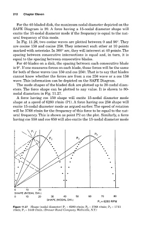
The mode shapes of the bladed disk are plotted up to 20-nodal diam-
eters. The force shape can be plotted to any value. It is shown to 80-
nodal diameters in Fig. 11.27.
A force having cos 15θ shape will excite 15-nodal diameter mode
shape at a speed of 6280 r/min (P1). A force having cos 25θ shape will
excite 15-nodal diameter mode as argued earlier. The speed of rotation
will be 3768 r/min for the frequency of this force to be equal to the nat-
ural frequency. This is shown as point P2 on the plot. Similarly, a force
having cos 55θ and cos 65θ will also excite the 15-nodal diameter mode
Figure 11.27 Shape (nodal diameter) P 1 = 6280 r/min; P 2 = 3768 r/min; P 3 = 1713
r/min; P 4 = 1449 r/min. (Dresser-Rand Company, Wellsville, N.Y.)