
Page 238 - Steam Turbines Design, Applications, and Rerating
P. 238
Campbell, Goodman, and SAFE Diagrams for Steam Turbine Blades 217
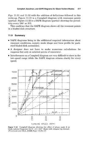
Figs. 11.31 and 11.32 with the addition of definitions followed in this
write-up. Figure 11.31 is a Campbell diagram with resonance points
(partial). Figure 11.32 is a SAFE diagram (partial) showing the period-
icity every 180° or N/2.
This confirms that the SAFE diagram shows all the resonant points
in a bladed disk structure.
11.9 Summary
■ SAFE diagrams bring in the additional required information about
resonant conditions, namely mode shape and force profile for pack-
eted bladed disk assemblies.
■ A designer does not have to make numerous calculations for
response but only at selected points of concern(s).
■ Interferences on a Campbell diagram are very difficult to show in the
low-speed range while the SAFE diagram retains clarity for every
speed.
Figure 11.32 Campbell diagram showing the effect of phase angle β on
blade natural frequency for 0°<β≤ 540° (blade with integral tip shroud).
(Provenzale and Skok, ASME Paper 73-Pet-17)