
Page 31 - Steam Turbines Design, Applications, and Rerating
P. 31
12 Chapter One
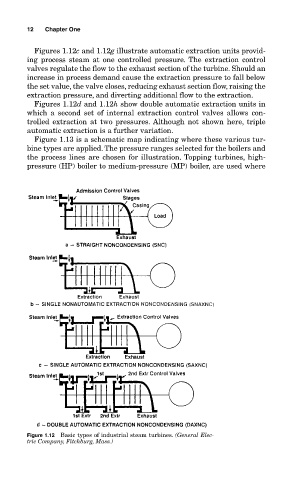
Figures 1.12c and 1.12g illustrate automatic extraction units provid-
ing process steam at one controlled pressure. The extraction control
valves regulate the flow to the exhaust section of the turbine. Should an
increase in process demand cause the extraction pressure to fall below
the set value, the valve closes, reducing exhaust section flow, raising the
extraction pressure, and diverting additional flow to the extraction.
Figures 1.12d and 1.12h show double automatic extraction units in
which a second set of internal extraction control valves allows con-
trolled extraction at two pressures. Although not shown here, triple
automatic extraction is a further variation.
Figure 1.13 is a schematic map indicating where these various tur-
bine types are applied. The pressure ranges selected for the boilers and
the process lines are chosen for illustration. Topping turbines, high-
pressure (HP) boiler to medium-pressure (MP) boiler, are used where
Figure 1.12 Basic types of industrial steam turbines. (General Elec-
tric Company, Fitchburg, Mass.)