
Page 33 - Steam Turbines Design, Applications, and Rerating
P. 33
14 Chapter One
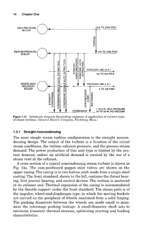
Figure 1.13 Schematic diagram illustrating regimens of application of various types
of steam turbines. (General Electric Company, Fitchburg, Mass.)
1.3.1 Straight noncondensing
The most simple steam turbine configuration is the straight noncon-
densing design. The output of the turbine is a function of the initial
steam conditions, the turbine exhaust pressure, and the process steam
demand. The power production of this unit type is limited by the pro-
cess demand, unless an artificial demand is created by the use of a
steam vent at the exhaust.
A cross section of a typical noncondensing steam turbine is shown in
Fig. 14a. The cam-positioned poppet inlet valves are shown on the
upper casing. The casing is in two halves, each made from a single steel
casting. The front standard, shown to the left, contains the thrust bear-
ing, first journal bearing, and control devices. The turbine is anchored
at its exhaust end. Thermal expansion of the casing is accommodated
by the flexible support under the front standard. The steam path is of
the impulse, wheel-and-diaphragm type, in which the moving buckets
are carried on the periphery of wheels machined from a solid forging.
The packing diameters between the wheels are made small to mini-
mize the interstage packing leakage. A small-diameter shaft acts to
minimize transient thermal stresses, optimizing starting and loading
characteristics.