
Page 36 - Steam Turbines Design, Applications, and Rerating
P. 36
Introduction 17
(d)
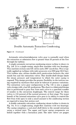
Figure 1.14 (Continued)
Automatic extraction/admission valve gear is normally used when
the extraction or admission flow is greater than 25 percent of the flow
through the turbine.
A single automatic extraction condensing steam turbine is shown in
Fig. 14b. It is a single-casing, single-flow machine with two bearings.
This machine utilizes cam-lift valves and a 360° nozzle box. This is typ-
ically applied on turbines with inlet pressures over 900 psig (62.0 bar).
This turbine also utilizes double-shell construction between the inlet
nozzle box and the extraction valves. This double-shell design limits
the steam pressure and temperature to which the outer casing is
exposed. This design provides the greater flexibility in the turbine cas-
ing required by machines that must be tolerant to process variations.
The extraction valve gear configuration in Fig. 14b is also a poppet
valve design with a bar lift mechanism. The chest is a fabricated design
that is partitioned to pass flow from each valve to a specified number
of nozzles in the extraction diaphragm. The control range for these
valves is ±10 percent of the normal pressure at that stage. The major
benefit of the internal extraction valve gear is its ability to control the
flow from wide open to only a small amount to the condensing section
as required to keep that section cool.
A double automatic extraction condensing steam turbine is shown in
Fig. 14c. It is a single-casing, single-flow machine with two bearings.
The casing comprises a cast-steel shell down to the second extraction
using a vertical joint. The upper and lower casing components are
bolted together with a horizontal joint. The inlet valves are poppet