Page 289 - Structural Steel Designers Handbook AISC, AASHTO, AISI, ASTM, and ASCE-07 Design Standards
P. 289

Brockenbrough_Ch06.qxd  9/29/05  5:15 PM  Page 6.11


                                                    DESIGN OF BUILDING MEMBERS


                                                                              DESIGN OF BUILDING MEMBERS  6.11

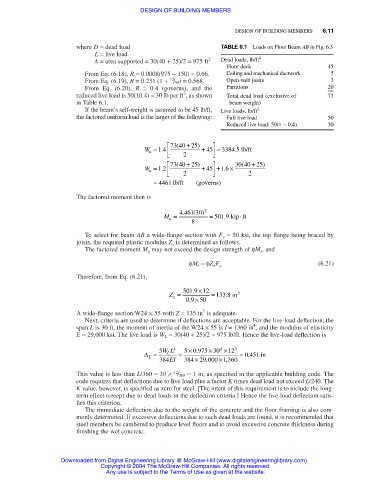
                                  where D = dead load                     TABLE 6.1 Loads on Floor Beam AB in Fig. 6.3
                                       L = live load                                 2
                                       A = area supported = 30(40 + 25)/2 = 975 ft 2  Dead loads, lb/ft
                                                                            Floor deck                  45
                                    From Eq. (6.18), R = 0.0008(975 − 150) = 0.66.  Ceiling and mechanical ductwork  5
                                                            73
                                    From Eq. (6.19), R = 0.231 (1 + / 50) = 0.568.  Open-web joists      3
                                    From Eq. (6.20),  R = 0.4 (governs), and the  Partitions            20
                                                                                                        ––
                                                                2
                                  reduced live load is 50(10.4) = 30 lb per ft , as shown  Total dead load (exclusive of  73
                                  in Table 6.1.                              beam weight)
                                    If the beam’s self-weight is assumed to be 45 lb/ft,  Live loads, lb/ft 2
                                  the factored uniform load is the larger of the following:  Full live load  50
                                                                            Reduced live load: 50(1 − 0.4)  30
                                                            73 40 + 25)  
                                                              (
                                                     W = 14 .     2  + 45    = 3384 5 .  lb/ft
                                                      u
                                                              (
                                                                                (
                                                            73 40 + 25)     30 40  + 25)
                                                     W = 12 .     2  + 45   +1 6 .  ×  2
                                                      u
                                                        = 4461 lb/ft  (governs)
                                  The factored moment then is
                                                                .
                                                                   (
                                                           M =  4 461 30) 2  = 501 9 .  kip ft
                                                                                ⋅
                                                            u
                                                                  8
                                    To select for beam AB a wide-flange section with F y = 50 ksi, the top flange being braced by
                                  joists, the required plastic modulus Z x is determined as follows.
                                    The factored moment M u may not exceed the design strength of φM r , and
                                                                                                      (6.21)
                                                                  φM r =φZ x F y
                                  Therefore, from Eq. (6.21),

                                                            Z =  501 9 .  ×12  = 133 8 . in 3
                                                             x
                                                                 09 .  × 50
                                                                     3
                                  A wide-flange section W24 × 55 with Z = 135 in is adequate.
                                    Next, criteria are used to determine if deflections are acceptable. For the live-load deflection, the
                                                                                    4
                                  span L is 30 ft, the moment of inertia of the W24 × 55 is I = 1360 in , and the modulus of elasticity
                                  E = 29,000 ksi. The live load is W L = 30(40 + 25)/2 = 975 lb/ft. Hence the live-load deflection is
                                                                       ×
                                                                    .
                                                     ∆ =  5 WL 4  =  5 × 0 975 30 4  ×12 3  = 0 451  in
                                                           L
                                                                                  .
                                                      L
                                                                      ,
                                                         384 EI  384 × 29 000  ×1 360
                                                                            ,
                                                             12
                                  This value is less than L/360 = 30 × / 360 = 1 in, as specified in the applicable building code. The
                                  code requires that deflections due to live load plus a factor K times dead load not exceed L/240. The
                                  K value, however, is specified as zero for steel. [The intent of this requirement is to include the long-
                                  term effect (creep) due to dead loads in the deflection criteria.] Hence the live-load deflection satis-
                                  fies this criterion.
                                    The immediate deflection due to the weight of the concrete and the floor framing is also com-
                                  monly determined. If excessive deflections due to such dead loads are found, it is recommended that
                                  steel members be cambered to produce level floors and to avoid excessive concrete thickness during
                                  finishing the wet concrete.
                              Downloaded from Digital Engineering Library @ McGraw-Hill (www.digitalengineeringlibrary.com)
                                         Copyright © 2004 The McGraw-Hill Companies. All rights reserved.
                                          Any use is subject to the Terms of Use as given at the website.
   284   285   286   287   288   289   290   291   292   293   294