Page 8 - Structural Steel Designers Handbook AISC, AASHTO, AISI, ASTM, and ASCE-07 Design Standards
P. 8

Brockenbrough_Ch01.qxd  9/29/05  4:59 PM  Page 1.6


                          PROPERTIES OF STRUCTURAL STEELS AND EFFECTS OF STEELMAKING AND FABRICATION


                   1.6  CHAPTER ONE

                               Steels furnished to this specification can provide a resistance to atmospheric corrosion up to four
                               times that of structural carbon steel depending on the grade.
                                 Constructional alloy steels are also frequently selected because of their ability to resist abra-
                               sion. For many types of abrasion, this resistance is related to hardness or tensile strength.
                               Therefore, constructional alloy steels may have nearly twice the resistance to abrasion provided
                               by carbon steel. Also available are numerous grades that have been heat treated to increase the
                               hardness even more.


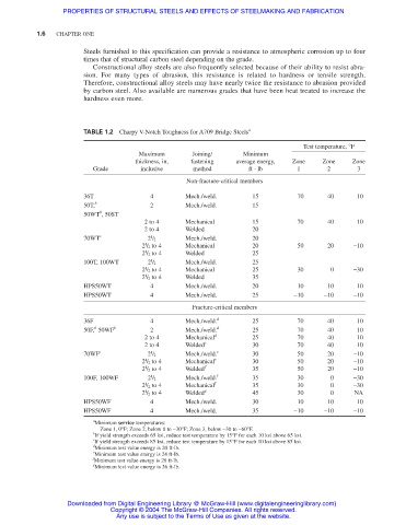
                               TABLE 1.2  Charpy V-Notch Toughness for A709 Bridge Steels a
                                                                                       Test temperature, °F
                                             Maximum       Joining/     Minimum
                                            thickness, in,  fastening  average energy,  Zone  Zone  Zone
                                 Grade       inclusive     method        ft ⋅ lb     1       2       3
                                                         Non-fracture-critical members
                               36T              4        Mech./weld.      15          70     40      10
                               50T, b           2        Mech./weld.      15
                                   b
                               50WT , 50ST
                                              2 to 4     Mechanical       15          70     40      10
                                              2 to 4     Welded           20
                                                1
                               70WT c          2 / 2     Mech./weld.      20
                                               1
                                              2 / 2 to 4  Mechanical      20          50     20     −10
                                              2 / 2 to 4  Welded          25
                                               1
                                                1
                               100T, 100WT     2 / 2     Mech./weld.      25
                                              2 / 2 to 4  Mechanical      25          30      0     −30
                                               1
                                               1
                                              2 / 2 to 4  Welded          35
                               HPS50WT          4        Mech./weld.      20          10     10      10
                               HPS50WT          4        Mech./weld.      25         −10    −10     −10
                                                           Fracture-critical members
                               36F              4        Mech./weld. d    25          70     40      10
                                  b
                               50F, 50WF b      2        Mech./weld. d    25          70     40      10
                                              2 to 4     Mechanical d     25          70     40      10
                                              2 to 4     Welded e         30          70     40      10
                                                1
                               70WF c          2 / 2     Mech./weld. e    30          50     20     −10
                                               1
                                              2 / 2 to 4  Mechanical e    30          50     20     −10
                                               1
                                              2 / 2 to 4  Welded  f       35          50     20     −10
                                                1
                               100F, 100WF     2 / 2     Mech./weld. f    35          30      0     −30
                                               1
                                              2 / 2 to 4  Mechanical f    35          30      0     −30
                                              2 / 2 to 4  Welded g        45          30      0     NA
                                               1
                               HPS50WF          4        Mech./weld.      30          10     10      10
                               HPS50WF          4        Mech./weld.      35         −10    −10     −10
                                 a
                                  Minimum service temperatures:
                                   Zone 1, 0°F; Zone 2, below 0 to −30°F; Zone 3, below −30 to −60°F.
                                 b
                                  If yield strength exceeds 65 ksi, reduce test temperature by 15°F for each 10 ksi above 65 ksi.
                                 c
                                  If yield strength exceeds 85 ksi, reduce test temperature by 15°F for each 10 ksi above 85 ksi.
                                 d
                                  Minimum test value energy is 20 ft-lb.
                                 e
                                  Minimum test value energy is 24 ft-lb.
                                 f
                                  Minimum test value energy is 28 ft-lb.
                                 g
                                  Minimum test value energy is 36 ft-lb.
                           Downloaded from Digital Engineering Library @ McGraw-Hill (www.digitalengineeringlibrary.com)
                                      Copyright © 2004 The McGraw-Hill Companies. All rights reserved.
                                       Any use is subject to the Terms of Use as given at the website.
   3   4   5   6   7   8   9   10   11   12   13