
Page 95 - Structural Steel Designers Handbook AISC, AASHTO, AISI, ASTM, and ASCE-07 Design Standards
P. 95
Brockenbrough_Ch03.qxd 9/29/05 5:05 PM Page 3.27
CONNECTIONS
CONNECTIONS 3.27
5
3
3
5
1
in / 4-in plate could be a minimum of / 4 + / 16 = 1 / 16 in. The depth of metal would be at least / 8 in,
3
because half the material thickness is only / 8 in.
Plug welds may not be spaced closer center-to-center than four times the hole diameter.
The length of the slot for a slot weld should not exceed 10 times the part thickness. The width of
5
the slot should be at least equal to the depth of the hole plus / 16 in, but the width should not exceed
1
2 / 4 times the weld thickness.
1
3
5
3
Thus, the width of the slot in / 4-in plate should be a minimum of / 4 + / 16 = 1 / 16 in. The weld
5
3
metal depth would be at least / 8 in, because half the material thickness is only / 8 in. The slot could
5
1
be up to 10 × / 8 = 6 / 4 in long.
Slot welds may be spaced no closer than four times their width in a direction transverse to the slot
length. In the longitudinal direction, center-to-center spacing should be at least twice the slot length.
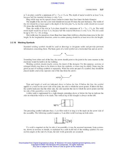
3.2.16 Welding Symbols
Standard welding symbols should be used on drawings to designate welds and provide pertinent
information concerning them. The basic parts of a weld symbol are a horizontal line and an arrow:
Extending from either end of the line, the arrow should point to the joint in the same manner as the
electrode would be held to do the welding.
Welding symbols should clearly convey the intent of the designer. For this purpose, sections or
enlarged details may have to be drawn to show the symbols, or notes may be added. Notes may be
given as part of welding symbols or separately. When the notes are part of a symbol, they should be
placed inside a tail at the opposite end of the line from the arrow:
Type and length of weld are indicated above or below the line. If below the line, the symbol
applies to a weld on the arrow side of the joint, the side to which the arrow points. If above the line,
the symbol indicates that the other side, the side opposite the one to which the arrow points (not the
far side of the assembly), is to be welded.
A fillet weld is represented by a right triangle extending above or below the line to indicate the
side on which the weld is to be made. The vertical leg of the triangle is always on the left.
1
The preceding symbol indicates that a / 4-in fillet weld 6 in long is to be made on the arrow side of
1
the assembly. The following symbol requires a / 4-in fillet weld 6 in long on both sides.
If a weld is required on the far side of an assembly, it may be assumed necessary from symme-
try, shown in sections or details, or explained by a note in the tail of the welding symbol. For con-
nection angles at the end of a beam, far-side welds generally are assumed:
Downloaded from Digital Engineering Library @ McGraw-Hill (www.digitalengineeringlibrary.com)
Copyright © 2004 The McGraw-Hill Companies. All rights reserved.
Any use is subject to the Terms of Use as given at the website.