
Page 98 - Structural Steel Designers Handbook AISC, AASHTO, AISI, ASTM, and ASCE-07 Design Standards
P. 98
Brockenbrough_Ch03.qxd 9/29/05 5:05 PM Page 3.30
CONNECTIONS
3.30 CHAPTER THREE
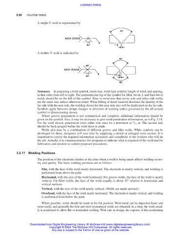
A single-V weld is represented by
A double-V weld is indicated by
Summary. In preparing a weld symbol, insert size, weld-type symbol, length of weld, and spacing,
in that order from left to right. The perpendicular leg of the symbol for fillet, bevel, J, and flare-bevel
welds should be on the left of the symbol. Bear in mind also that arrow-side and other-side welds
are the same size, unless otherwise noted. When billing of detail material discloses the identity of the
far side with the near side, the welding shown for the near side also will be duplicated on the far side.
Symbols apply between abrupt changes in direction of welding unless governed by the all-around
symbol or dimensioning shown.
Where groove preparation is not symmetrical and complete, additional information should be
given on the symbol. Also, it may be necessary to give weld-penetration information, as in Fig. 3.18.
3
For the weld shown, penetration from either side must be a minimum of / 16 in. The second side
should be back-gouged before the weld there is made.
Welds also may be a combination of different groove and fillet welds. While symbols can be
developed for these, designers will save time by supplying a sketch or enlarged cross section. It is
important to convey the required information accurately and completely to the workers who will do
the job. Actually, it is common practice for designers to indicate what is required of the weld and for
fabricators and erectors to submit proposed procedures.
3.2.17 Welding Positions
The position of the electrode relative to the joint when a weld is being made affects welding econo-
my and quality. The basic welding positions are as follows:
Flat, with the face of the weld nearly horizontal. The electrode is nearly vertical, and welding is
performed from above the joint.
Horizontal, with the axis of the weld horizontal. For groove welds, the face of the weld is nearly
vertical. For fillet welds, the face of the weld usually is about 45° relative to horizontal and
vertical surfaces.
Vertical, with the axis of the weld nearly vertical. (Welds are made upward.)
Overhead, with the face of the weld nearly horizontal. The electrode is nearly vertical, and welding
is performed from below the joint.
Where possible, welds should be made in the flat position. Weld metal can be deposited faster and
more easily, and generally the best and most economical welds are obtained. In a shop, the work usual-
ly is positioned to allow flat or horizontal welding. With care in design, the expense of this positioning
Downloaded from Digital Engineering Library @ McGraw-Hill (www.digitalengineeringlibrary.com)
Copyright © 2004 The McGraw-Hill Companies. All rights reserved.
Any use is subject to the Terms of Use as given at the website.