
Page 103 - Structural Steel Designers Handbook AISC, AASHTO, AISI, ASTM, and ASCE-07 Design Standards
P. 103
Brockenbrough_Ch03.qxd 9/29/05 5:05 PM Page 3.35
CONNECTIONS
CONNECTIONS 3.35
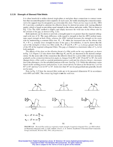
3.2.20 Strength of Skewed Fillet Welds
It is often beneficial to utilize skewed single-plate or end-plate shear connections to connect mem-
bers that run nonorthogonal to their supports. In such cases, the welds attaching the connection mate-
rial to the support must be designed to accommodate this skew. There are two ways to do this. AWS
D1.1 provides a method to calculate the effective throat for skewed tee joints with varying dihedral
angles, which is based on providing equal strength in the obtuse and acute welds. This is shown in
Fig. 3.22a. The AISC method is simpler, and simply increases the weld size on the obtuse side by
the amount of the gap, as shown in Fig. 3.22c.
Both methods can be shown to provide a strength equal to or greater than the required orthog-
onal weld size of W. The main difference with regard to strength is that the AWS method main-
tains equal strength in both fillets, whereas the AISC method increases the strength on the acute
side by maintaining a constant fillet size, W a = W, while the increased size on the obtuse side,
W o = W + g, actually loses strength because of the gap g. Nevertheless, it can be shown that the
sum of the strengths of these two fillet welds, W a = W and W o = W + g, is always greater than that
3
of the 2W of the required orthogonal fillets. The gap g is limited to a maximum value of / 16 in for
both methods.
The effects of the skew on the effective throat of a fillet weld can be very significant, as shown
in Fig. 3.23. Figure 3.23 also shows how fillet legs W o and W a are measured in the skewed configu-
ration. On the acute side of the connection the effective throat for a given fillet weld size increases
gradually as the connection intersection angle, φ, changes from 90° to 60°. From 60° to 30°, the weld
changes from a fillet weld to a partial-penetration groove weld and the effective throat t e decreases
due to the allowance z for the unwelded portion at the root. See Fig. 3.24. While this allowance varies
based on the welding process and position, it can conservatively be taken as the throat less / 8 in for
1
1
60° to 45° and less / 4 in for 45° to 30°. Joints less than 30° are not prequalified and generally should
not be used.
Note in Fig. 3.23 how the skewed fillet welds are to be measured (dimension W) in accordance
with AWS and AISC. The contact leg length is not the weld size.
FIGURE 3.22 Skewed fillet weld sizes required to match strength of required orthogonal fillets. (a) AWS method.
(b) Required orthogonal weld. (c) AISC method. (Source: A. R. Tamboli, Handbook of Structural Steel Connection
Design and Details, McGraw-Hill, 1999, with permission.)
Downloaded from Digital Engineering Library @ McGraw-Hill (www.digitalengineeringlibrary.com)
Copyright © 2004 The McGraw-Hill Companies. All rights reserved.
Any use is subject to the Terms of Use as given at the website.