Page 105 - Structural Steel Designers Handbook AISC, AASHTO, AISI, ASTM, and ASCE-07 Design Standards
P. 105

Brockenbrough_Ch03.qxd  9/29/05  5:05 PM  Page 3.37


                                                           CONNECTIONS


                                                                                          CONNECTIONS  3.37

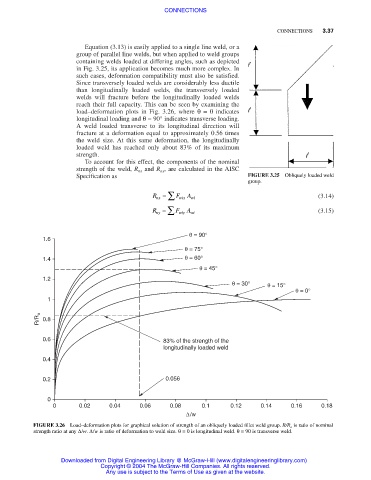
                                    Equation (3.13) is easily applied to a single line weld, or a
                                  group of parallel line welds, but when applied to weld groups
                                  containing welds loaded at differing angles, such as depicted
                                  in Fig. 3.25, its application becomes much more complex. In
                                  such cases, deformation compatibility must also be satisfied.
                                  Since transversely loaded welds are considerably less ductile
                                  than longitudinally loaded welds, the transversely loaded
                                  welds will fracture before the longitudinally loaded welds
                                  reach their full capacity. This can be seen by examining the
                                  load–deformation plots in Fig. 3.26, where  θ= 0 indicates
                                  longitudinal loading and θ= 90° indicates transverse loading.
                                  A weld loaded transverse to its longitudinal direction will
                                  fracture at a deformation equal to approximately 0.56 times
                                  the weld size. At this same deformation, the longitudinally
                                  loaded weld has reached only about 83% of its maximum
                                  strength.
                                    To account for this effect, the components of the nominal
                                  strength of the weld, R nx and R ny , are calculated in the AISC
                                  Specification as                                 FIGURE 3.25  Obliquely loaded weld
                                                                                  group.
                                                        nx ∑
                                                       R =    F   A wi                                (3.14)
                                                               wix
                                                        ny ∑
                                                       R =    F   A wi                                (3.15)
                                                               wiy

                                                                  θ = 90°
                         1.6
                                                                θ = 75°
                         1.4                                    θ = 60°
                                                                    θ = 45°
                         1.2
                                                                              θ = 30°  θ = 15°
                                                                                               θ = 0°
                          1

                        R/R o  0.8


                         0.6                              83% of the strength of the
                                                          longitudinally loaded weld
                         0.4


                         0.2                               0.056

                          0
                            0      0.02    0.04     0.06    0.08     0.1     0.12     0.14    0.16     0.18
                                                                 ∆/w
                      FIGURE 3.26 Load–deformation plots for graphical solution of strength of an obliquely loaded fillet weld group. R/R o is ratio of nominal
                      strength ratio at any ∆/w. ∆/w is ratio of deformation to weld size. θ= 0 is longitudinal weld. θ= 90 is transverse weld.


                              Downloaded from Digital Engineering Library @ McGraw-Hill (www.digitalengineeringlibrary.com)
                                         Copyright © 2004 The McGraw-Hill Companies. All rights reserved.
                                          Any use is subject to the Terms of Use as given at the website.
   100   101   102   103   104   105   106   107   108   109   110