
Page 102 - Structural Steel Designers Handbook AISC, AASHTO, AISI, ASTM, and ASCE-07 Design Standards
P. 102
Brockenbrough_Ch03.qxd 9/29/05 5:05 PM Page 3.34
CONNECTIONS
3.34 CHAPTER THREE
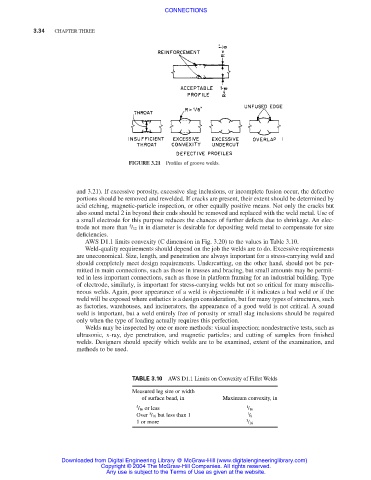
FIGURE 3.21 Profiles of groove welds.
and 3.21). If excessive porosity, excessive slag inclusions, or incomplete fusion occur, the defective
portions should be removed and rewelded. If cracks are present, their extent should be determined by
acid etching, magnetic-particle inspection, or other equally positive means. Not only the cracks but
also sound metal 2 in beyond their ends should be removed and replaced with the weld metal. Use of
a small electrode for this purpose reduces the chances of further defects due to shrinkage. An elec-
5
trode not more than / 32 in in diameter is desirable for depositing weld metal to compensate for size
deficiencies.
AWS D1.1 limits convexity (C dimension in Fig. 3.20) to the values in Table 3.10.
Weld-quality requirements should depend on the job the welds are to do. Excessive requirements
are uneconomical. Size, length, and penetration are always important for a stress-carrying weld and
should completely meet design requirements. Undercutting, on the other hand, should not be per-
mitted in main connections, such as those in trusses and bracing, but small amounts may be permit-
ted in less important connections, such as those in platform framing for an industrial building. Type
of electrode, similarly, is important for stress-carrying welds but not so critical for many miscella-
neous welds. Again, poor appearance of a weld is objectionable if it indicates a bad weld or if the
weld will be exposed where esthetics is a design consideration, but for many types of structures, such
as factories, warehouses, and incinerators, the appearance of a good weld is not critical. A sound
weld is important, but a weld entirely free of porosity or small slag inclusions should be required
only when the type of loading actually requires this perfection.
Welds may be inspected by one or more methods: visual inspection; nondestructive tests, such as
ultrasonic, x-ray, dye penetration, and magnetic particles; and cutting of samples from finished
welds. Designers should specify which welds are to be examined, extent of the examination, and
methods to be used.
TABLE 3.10 AWS D1.1 Limits on Convexity of Fillet Welds
Measured leg size or width
of surface bead, in Maximum convexity, in
5 / 16 or less 1 / 16
5
Over / 16 but less than 1 1 / 8
1 or more 3 / 16
Downloaded from Digital Engineering Library @ McGraw-Hill (www.digitalengineeringlibrary.com)
Copyright © 2004 The McGraw-Hill Companies. All rights reserved.
Any use is subject to the Terms of Use as given at the website.