
Page 148 - Structural Steel Designers Handbook AISC, AASHTO, AISI, ASTM, and ASCE-07 Design Standards
P. 148
Brockenbrough_Ch03.qxd 9/29/05 5:05 PM Page 3.80
CONNECTIONS
3.80 CHAPTER THREE
Doublers. The beam flange force (required strength) delivered to the column is F f = 229 kips. The
design shear strength of the column is
φV v =φ× 0.60 × F y d c t w = 0.90 × 0.60 × 50 × 14.2 × 0.485 = 186 kips < 229 kips
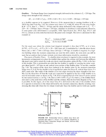
so a doubler appears to be required. However, if the moment that is causing doublers is M 1 =
389 ft⋅kip, then from Fig. 3.45, the column story shear is V s =φM p /H, where H is the story height.
If H = 13 ft, then V s = 389/13 = 30 kips and the shear delivered to the column web is F f − V s =
229 − 30 = 199 kips. Since 199 kips > 185 kips, a doubler (or doublers) is still indicated. However,
if some panel zone deformation is acceptable, AISC Specification Sec. J10.6, Eqs. J10.11 and
J10.12, contain an extra term that increases the panel zone strength. The term is calculated for this
example as
×
3bt 2 3 146 0780 2
× .
.
0 184
f c f c = = .
×
.
.
× .
dd t 21 0 14 2 0 485
b cwc
For the usual case where the column load (required strength) is less than 0.75P y , as it is here,
(0.75P y = 0.75 × A c F yc = 0.75 × 29.1 × 50 = 1091 kips), φV v is multiplied by 1 plus the above factor.
Hence, φV v = 186 × 1.184 = 220 kips. Since 220 kips > 199 kips, no doubler is required. In a high-
rise building where the moment connections are used for drift control, the extra term can still be
used, but an analysis that includes inelastic joint shear deformation should be considered.
Placement of Doubler Plates. If a doubler plate (or plates) is required in this example, the most
inexpensive arrangement is to place the doubler plate against the column web between the stiffeners
(the panel zone) and to attach the weak-axis shear connection plates, plates B (Fig. 3.44b), to the face
of the doubler. This is permissible provided that the doubler is capable of carrying the entire weak-
axis shear load R = 163 kips on one vertical cross section of the doubler plate. To see this, consider
Fig. 3.46. The portion of the shear force induced in the doubler plate by the moment-connection
flange force F f is H. For the doubler to be in equilibrium under the forces H, vertical shear forces V =
Hd/w must exist. The welds of the doubler at its four edges develop the shear strength of the dou-
bler. Let the shear force R from the weak axis connection be applied to the face of the doubler at or
near its horizontal center as shown in Fig. 3.46. If it is required that all of the shear R can be carried
by one vertical section a–a of Fig. 3.46, that is, 0.90 × 0.60 × F y t d d ≥ R, where t d is the doubler thick-
ness and F y is the yield stress of the doubler (and the column), then the free-body diagram of Fig. 3.46
is possible. In this figure, all of the shear force R is delivered to the side of the doubler where
it is opposite in direction to the shear delivered by the moment connection, thereby avoiding over-
stressing the other side where the two shears would add. Since the doubler and its welds are capable
FIGURE 3.45 Relationship between column story shear and
moments that induce it. (Source: A. R. Tamboli, Handbook of
Structural Steel Connection Design and Details, McGraw-Hill,
1999, with permission.)
Downloaded from Digital Engineering Library @ McGraw-Hill (www.digitalengineeringlibrary.com)
Copyright © 2004 The McGraw-Hill Companies. All rights reserved.
Any use is subject to the Terms of Use as given at the website.