
Page 23 - Structural Steel Designers Handbook AISC, AASHTO, AISI, ASTM, and ASCE-07 Design Standards
P. 23
Brockenbrough_Ch01.qxd 9/29/05 4:59 PM Page 1.21
PROPERTIES OF STRUCTURAL STEELS AND EFFECTS OF STEELMAKING AND FABRICATION
STRUCTURAL STEELS, STEELMAKING, AND FABRICATION 1.21
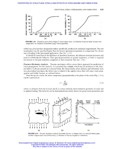
FIGURE 1.10 Transition curves from Charpy-V notch impact tests. (a) Variation of percent shear fracture with
temperature, (b) Variation of absorbed energy with temperature.
within any given product designation unless specifically produced to minimum requirements. The test
temperature may be specified higher than the lowest operating temperature to compensate for a lower
rate of loading in the anticipated application. (See Art. 1.1.5.)
It should be noted that as the thickness of members increases, the inherent restraint increases and
tends to inhibit ductile behavior. Thus special precautions or greater toughness, or both, is required
for tension or flexural members comprised of thick material. (See Art. 1.16.)
Fracture-Mechanics Analysis. Fracture mechanics offers a more direct approach for prediction of
crack propagation. For this analysis, it is assumed that a crack, which may be defined as a flat, inter-
nal defect, is always present in a stressed body. By linear-elastic stress analysis and laboratory tests
on a precracked specimen, the defect size is related to the applied stress that will cause crack prop-
agation and brittle fracture, as outlined below.
Near the tip of a crack, the stress component f perpendicular to the plane of the crack (Fig. 1.11a)
can be expressed as
f = K l (1.2)
2p r
where r is distance from tip of crack and K l is a stress-intensity factor related to geometry of crack and
to applied loading. The factor K l can be determined from elastic theory for given crack geometries and
FIGURE 1.11 Fracture mechanics analysis for brittle fracture. (a) Sharp crack in a stressed infinite plate.
(b) Disk-shaped crack in an infinite body. (c) Relation of fracture toughness to thickness.
Downloaded from Digital Engineering Library @ McGraw-Hill (www.digitalengineeringlibrary.com)
Copyright © 2004 The McGraw-Hill Companies. All rights reserved.
Any use is subject to the Terms of Use as given at the website.