
Page 267 - Structural Steel Designers Handbook AISC, AASHTO, AISI, ASTM, and ASCE-07 Design Standards
P. 267
Brockenbrough_Ch05.qxd 9/29/05 5:12 PM Page 5.47
CRITERIA FOR BUILDING DESIGN
CRITERIA FOR BUILDING DESIGN 5.47
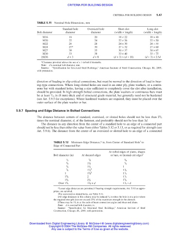
TABLE 5.11 Nominal Hole Dimensions, mm
Standard hole Oversized hole Short-slot Long-slot
Bolt diameter diameter diameter (width × length) (width × length)
M16 18 20 18 × 22 18 × 40
M20 22 24 22 × 26 22 × 50
M22 24 28 24 × 30 24 × 55
M24 27* 30 27 × 32 27 × 60
M27 30 35 30 × 37 30 × 67
M30 33 38 33 × 40 33 × 75
≥M36 d + 3 d + 8 (d + 3) × (d + 10) (d + 3) × 2.5d
*Clearance provided allows the use of a 1-in bolt if desirable.
Note: d is nominal bolt diameter, mm.
Source: “Specification for Structural Steel Buildings,” American Institute of Steel Construction, Chicago, Ill., 2005,
with permission.
direction of loading in slip-critical connections, but must be normal to the direction of load in bear-
ing-type connections. Where long-slotted holes are used in an outer ply, plate washers, or a contin-
uous bar with standard holes, having a size sufficient to completely cover the slot after installation,
should be provided. In high-strength bolted connections, the plate washers or continuous bars must
5
be at least / 16 in (8 mm) thick and of structural-grade material, but generally need not be hardened
(see Art. 5.9.5 for exceptions). Where hardened washers are required, they must be placed over the
outer surface of the plate washer or bar.
5.9.7 Spacing and Edge Distance in Bolted Connections
2
The distance between centers of standard, oversized, or slotted holes should not be less than 2 / 3
times the nominal diameter, d, of the fastener, and preferably should not be less than 3d.
The distance in any direction from the center of a standard hole to an edge of a connected part
should not be less than either the value from either Tables 5.12 or 5.13, or as required for strength (see
Art. 5.9.8). The distance from the center of an oversized or slotted hole to an edge of a connected
†
TABLE 5.12 Minimum Edge Distance,* in, from Center of Standard Hole to
Edge of Connected Part
At rolled edges of plates, shapes
Bolt diameter (in) At sheared edges or bars, or thermal-cut edges ‡
1 7 3
/ 2 / 8 / 4
5 1 7
/ 8 1 / 8 / 8
3 1 1
/ 4 1 / 4
7 1 § 1
/ 8 1 / 2 1 / 8
3 §
1 1 / 4 1 / 4
1
1 2 1
1 / 8 1 / 2
1 1 5
1 / 4 2 / 4 1 / 8
1 1 / 4 × d 1 / 4 × d
1
3
Over 1 / 4
*Lesser edge distances are permitted if bearing strength requirements, Art. 5.9.8 as appro-
priate, are satisfied.
†For oversized or slotted holes, see Table 5.14.
1
‡All edge distances in this column may be reduced / 8 in when the hole is at a point where
the required strength does not exceed 25% of the maximum strength in the element.
1
§These may be 1 / 4 in at the ends of beam connection angles and shear end plates.
Note: d is nominal bolt diameter, in.
Source: “Specification for Structural Steel Buildings,” American Institute of Steel
Construction, Chicago, Ill., 2005, with permission.
Downloaded from Digital Engineering Library @ McGraw-Hill (www.digitalengineeringlibrary.com)
Copyright © 2004 The McGraw-Hill Companies. All rights reserved.
Any use is subject to the Terms of Use as given at the website.