
Page 268 - Structural Steel Designers Handbook AISC, AASHTO, AISI, ASTM, and ASCE-07 Design Standards
P. 268
Brockenbrough_Ch05.qxd 9/29/05 5:12 PM Page 5.48
CRITERIA FOR BUILDING DESIGN
5.48 CHAPTER FIVE
†
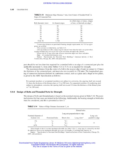
TABLE 5.13 Minimum Edge Distance,* mm, from Center of Standard Hole to
Edge of Connected Part
At rolled edges of plates, shapes
Bolt diameter (mm) At sheared edges or bars, or thermal-cut edges ‡
16 28 22
20 34 26
§
22 38 28
24 42 § 30
27 48 34
30 52 38
36 64 46
Over 36 1.75d 1.25d
*Lesser edge distances are permitted if bearing strength requirements, Art. 5.9.8 as appro-
priate, are satisfied.
†For oversized or slotted holes, see Table 5.15.
‡All edge distances in this column may be reduced 3 mm when the hole is at a point where
required strength does not exceed 25% of the maximum strength in the element.
§These may be 32 mm at the ends of beam connection angles and shear end plates.
Note: d is nominal bolt diameter, mm.
Source: “Specification for Structural Steel Buildings,” American Institute of Steel
Construction, Chicago, Ill., 2005, with permission.
part should be not less than that required for a standard hole to an edge of a connected part plus the
applicable increment C 2 from either Tables 5.14 or 5.15, or as required for strength.
The maximum distance from the center of a bolt to the nearest edge of parts in contact is 12 times
the thickness of the connected part, and must also not exceed 6 in (150 mm). The longitudinal spac-
ing of connectors between elements in continuous contact, such as a plate and a shape or two plates,
is given by the AISC Specification as follows:
For painted members or unpainted members not subject to corrosion, the spacing shall not exceed
24 times the thickness of the thinner plate or 12 in (305 mm). For unpainted members of weathering steel
subject to atmospheric corrosion, the spacing shall not exceed 14 times the thickness of the thinner plate
or 7 in (180 mm).
5.9.8 Design of Bolts and Threaded Parts for Strength
The design of bolts and threaded parts is based on the nominal stresses given in Table 5.16. The nom-
inal stresses for four cases are treated in the following. Additionally, the bearing strength at bolt holes
must be considered, and this is presented as item 5.
TABLE 5.14 Values of Edge Distance Increment C 2 , in
Slotted holes
Long axis perpendicular to edge
Nominal diameter of Long axis
fastener (in) Oversized holes Short slots Long slots* parallel to edge
7 1 1 / 8
≤ / 8 / 16 1
1 1 / 8 / 8 3 / 4d 0
1 1 3 / 16
≥1 / 8 / 8
*When length of slot is less than maximum allowable (see Table 5.10), C 2 values may be reduced by one-half
the difference between the maximum allowable and actual slot lengths; d is nominal bolt diameter, in.
Source: “Specification for Structural Steel Buildings,” American Institute of Steel Construction, Chicago, Ill.,
2005, with permission.
Downloaded from Digital Engineering Library @ McGraw-Hill (www.digitalengineeringlibrary.com)
Copyright © 2004 The McGraw-Hill Companies. All rights reserved.
Any use is subject to the Terms of Use as given at the website.