
Page 269 - Structural Steel Designers Handbook AISC, AASHTO, AISI, ASTM, and ASCE-07 Design Standards
P. 269
Brockenbrough_Ch05.qxd 9/29/05 5:12 PM Page 5.49
CRITERIA FOR BUILDING DESIGN
CRITERIA FOR BUILDING DESIGN 5.49
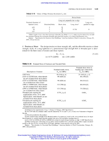
TABLE 5.15 Values of Edge Distance Increment C 2 , mm
Slotted holes
Long axis perpendicular to edge
Nominal diameter of Long axis
fastener (mm) Oversized holes Short slots Long slots* parallel to edge
≤22 2 3
24 3 3 0.75d 0
≥27 3 5
*When length of slot is less than maximum allowable (see Table 5.11), C 2 values may be reduced by one-half
the difference between the maximum allowable and actual slot lengths; d is nominal bolt diameter, mm.
Source: “Specification for Structural Steel Buildings,” American Institute of Steel Construction, Chicago, Ill.,
2005, with permission.
1. Tension or Shear. The design tension or shear strength, φR n , and the allowable tension or shear
strength, R n /Ω, of a snug-tightened or a pretensioned high-strength bolt or threaded part is deter-
mined for the limit states of tension and shear rupture:
(5.143)
R n = F n A b
φ= 0.75 (LRFD) Ω= 2.00 (ASD)
TABLE 5.16 Nominal Stress of Fasteners and Threaded Parts
Nominal shear stress in
Nominal tensile stress, bearing-type connections,
Description of fastener F nt , ksi (MPa) F nv , ksi (MPa)
A307 bolts 45 (310) [a, b] 24 (165) [b, c, f]
A325 or A325M bolts, when threads 90 (620) [e] 48 (330) [f]
are not excluded from shear planes
A325 or A325M bolts, when threads 90 (620) [e] 60 (414) [f]
are excluded from shear planes
A490 or A490M bolts, when threads 113 (780) [e] 60 (414) [f]
are not excluded from shear planes
A490 or A490M bolts, when threads 113 (780) [e] 75 (520) [f]
are excluded from shear planes
Threaded parts meeting the 0.75F u [a, d] 0.40F u
requirements of Sec. A3.4, AISC
Specification, when threads are not
excluded from shear planes
Threaded parts meeting the 0.75F u [a, d] 0.50F u
requirements of Sec. A3.4, AISC
Specification, when threads are
excluded from shear planes
[a] Subject to the requirements of App. 3, Design for Fatigue, AISC Specification.
1
[b] For A307 bolts the tabulated values must be reduced by 1% for each / 16 in (1.6 mm) over 5 diameters of length in
the grip.
[c] Threads permitted in shear planes.
[d] The nominal tensile strength of the threaded portion of an upset rod, based on the cross-sectional area at its major
thread diameter A D , must be larger than the nominal body area of the rod before upsetting times F y .
[e] For A325 or A325M and A490 or A490M bolts subject to tensile fatigue loading, see App. 3, AISC Specification.
[f] When bearing-type connections used to splice tension members have a fastener pattern whose length, measured
parallel to the line of force, exceeds 50 in (1270 mm), tabulated values must be reduced by 20%.
Source: “Specification for Structural Steel Buildings,” American Institute of Steel Construction, Chicago, Ill.,
2005, with permission.
Downloaded from Digital Engineering Library @ McGraw-Hill (www.digitalengineeringlibrary.com)
Copyright © 2004 The McGraw-Hill Companies. All rights reserved.
Any use is subject to the Terms of Use as given at the website.