
Page 235 - Sustainability in the Process Industry Integration and Optimization
P. 235
212 Cha p te r N i n e
systems containing mechanical, electrical, electronic, hydraulic,
thermal, control, power, and/or process-oriented subcomponents
(Modelica, 2009a; Modelica, 2009b). The free Modelica language is
developed by the nonprofit Modelica Association. In this language,
models are described by classes, which may contain differential,
algebraic, and discrete equations alongside properties and algorithms.
The language can be used for “hardware in the loop” simulations
and for embedded control systems (Modelica, 2009a). Modelica
supports high-level modeling by composing complex models from
detailed, component models. Models of standard components are
typically available in model libraries. A model can be defined by
using a graphical model editor offered by the various language
implementations (Modelica, 2010) to draw a composition diagram:
positioning icons that represent the model components, drawing
connections between the components; and providing parameter
values in dialogue boxes (Modelica, 2009b). Constructs for including
graphical annotations in Modelica render the icons and composition
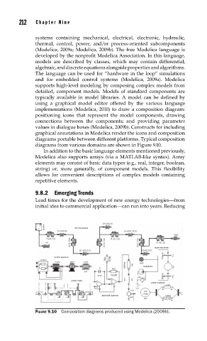
diagrams portable between different platforms. Typical composition
diagrams from various domains are shown in Figure 9.10.
In addition to the basic language elements mentioned previously,
Modelica also supports arrays (via a MATLAB-like syntax). Array
elements may consist of basic data types (e.g., real, integer, boolean,
string) or, more generally, of component models. This flexibility
allows for convenient descriptions of complex models containing
repetitive elements.
9.8.2 Emerging Trends
Lead times for the development of new energy technologies—from
initial idea to commercial application—can run into years. Reducing
b3={0,0,0}
y
3D mechanics
x
b1={0,0,0} b4={0,0.73,0}
Inertial
load
r1={0,1,0} r4={0,1,0}
b0 r2={1,0,0} r3={1,0,0} r5={1,0,0} r6={0,1,0}
state machines
b2={0,0.5,0} b5={0,0,0}
time>3 T2
control systems R=50
control Rp2
motor gear load
VolP
1 R=250 Ra hydraulics P4
C Rp1
J=1 q
C=C R=200 time>5
Rel T4
power trains L=L La
power systems
T1 Line1
p1 p2 p3 k=k 3rd
Order
electrical systems Line2
emf
G2
FIGURE 9.10 Composition diagrams produced using Modelica (2009b).