
Page 112 - Sustainable On-Site CHP Systems Design, Construction, and Operations
P. 112
90 CHP B a s i c s
The following analysis results illustrate the performance benefits of expanded func-
tionality packaged CHP systems. Consider three packaged CHP systems:
• System 1 can deliver electrical and hot water energies
• System 2 can deliver electrical and chilling (i. e., air-conditioning) energies
• System 3 can deliver electrical, and either hot water or chilling energies
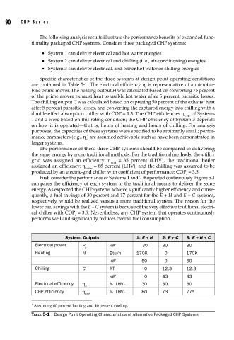
Specific characteristics of the three systems at design point operating conditions
are contained in Table 5-1. The electrical efficiency η is representative of a microtur-
e
bine prime mover. The heating output H was calculated based on converting 75 percent
of the prime mover exhaust heat to usable hot water after 5 percent parasitic losses.
The chilling output C was calculated based on capturing 50 percent of the exhaust heat
after 5 percent parasitic losses, and converting the captured energy into chilling with a
double-effect absorption chiller with COP = 1.3. The CHP efficiencies η of Systems
CHP
1 and 2 were based on this rating condition; the CHP efficiency of System 3 depends
on how it is operated—that is, hours of heating and hours of chilling. For analysis
purposes, the capacities of these systems were specified to be arbitrarily small; perfor-
mance parameters (e.g., η ) are assumed achievable such as have been demonstrated in
e
larger systems.
The performance of these three CHP systems should be compared to delivering
the same energy by more traditional methods. For the traditional methods, the utility
grid was assigned an efficiency: η grid = 35 percent (LHV), the traditional boiler
assigned an efficiency: η = 88 percent (LHV), and the chilling was assumed to be
boiler
produced by an electric-grid chiller with coefficient of performance: COP = 3.5.
e
First, consider the performance of Systems 1 and 2 if operated continuously. Figure 5-1
compares the efficiency of each system to the traditional means to deliver the same
energy. As expected the CHP systems achieve significantly higher efficiency and conse-
quently, a fuel savings of 30 percent and 17 percent for the E + H and E + C systems,
respectively, would be realized versus a more traditional system. The reason for the
lower fuel savings with the E + C system is because of the very effective traditional electri-
cal chiller with COP = 3.5. Nevertheless, any CHP system that operates continuously
e
performs well and significantly reduces overall fuel consumption.
System: Outputs 1: E + H 2: E + C 3: E + H + C
Electrical power P kW 30 30 30
e
Heating H Btu/h 170K 0 170K
kW 50 0 50
Chilling C RT 0 12.3 12.3
kW 0 43 43
Electrical efficiency η % (LHV) 30 30 30
e
CHP efficiency η % (LHV) 80 73 77 ∗
CHP
∗ Assuming 60 percent heating and 40 percent cooling.
TABLE 5-1 Design Point Operating Characteristics of Alternative Packaged CHP Systems