Page 148 - Sustainable On-Site CHP Systems Design, Construction, and Operations
P. 148

Natural gas
                               Primary  injection      Pilot diffusion flame
                                air inlet      Premixing  Diffusion
                                                 zone      zone


                              Pilot fuel
                                     Primary air  Combustor
                                       swirler   primary zone  Dilution
                                                            air injection
                                       Recirculation zone     ports
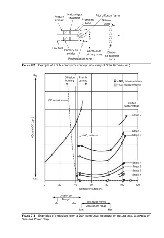
             FIGURE 7-2  Example of a DLN combustor concept. (Courtesy of Solar Turbines Inc.)


                   High
                                     Diffusion  Premix
                                      burning  burning             = NO x  measurements
                                                                   = CO measurements


                            CO emission
                                                                        Pilot fuel
                                                                       fraction/stage

                                                                           Stage 7
                    NO x  and CO (ppm)          NO x  emission             Stage 6


                                                                           Stage 5


                                                                           Stage 4
                                                                           Stage 3
                                                                           Stage 2
                                                                           Stage 1
                    Low
                          0       20       40      60       80      100      120
                                             Generator output (%)

                                   Dilution air
                                    Range
                                                  Inlet guide venes
                                Max      Min
                                                 Adjustment range
                                              Min             Max
             FIGURE 7-3  Examples of emissions from a DLN combustor operating on natural gas. (Courtesy of
             Siemens Power Corp.)
   143   144   145   146   147   148   149   150   151   152   153