
Page 151 - Sustainable On-Site CHP Systems Design, Construction, and Operations
P. 151
124 CHP B a s i c s
HRSG
drum Stack No x /O 3
monitor
Fuel Superheater Boiler Economizer
Air
FM
SCR
Exhaust
gas
Gas turbine
TIC
No x
monitor
Accumulator
Vaporizer
FC
S
Ammonia storage tank
NH 3
NH 3 /Air mixer flow- Legend:
Dillution air blower
control FC - Flow control
valve TIC - Temp indicator control
FM - Fuel meter
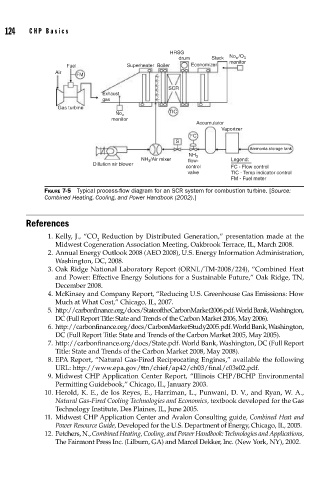
FIGURE 7-5 Typical process-fl ow diagram for an SCR system for combustion turbine. [Source:
Combined Heating, Cooling, and Power Handbook (2002).]
References
1. Kelly, J., “CO Reduction by Distributed Generation,” presentation made at the
2
Midwest Cogeneration Association Meeting, Oakbrook Terrace, IL, March 2008.
2. Annual Energy Outlook 2008 (AEO 2008), U.S. Energy Information Administration,
Washington, DC, 2008.
3. Oak Ridge National Laboratory Report (ORNL/TM-2008/224), “Combined Heat
and Power: Effective Energy Solutions for a Sustainable Future,” Oak Ridge, TN,
December 2008.
4. McKinsey and Company Report, “Reducing U.S. Greenhouse Gas Emissions: How
Much at What Cost,” Chicago, IL, 2007.
5. http://carbonfinance.org/docs/StateoftheCarbonMarket2006.pdf. World Bank, Washington,
DC (Full Report Title: State and Trends of the Carbon Market 2006, May 2006).
6. http://carbonfinance.org/docs/CarbonMarketStudy2005.pdf. World Bank, Washington,
DC (Full Report Title: State and Trends of the Carbon Market 2005, May 2005).
7. http://carbonfinance.org/docs/State.pdf. World Bank, Washington, DC (Full Report
Title: State and Trends of the Carbon Market 2008, May 2008).
8. EPA Report, “Natural Gas-Fired Reciprocating Engines,” available the following
URL: http://www.epa.gov/ttn/chief/ap42/ch03/final/c03s02.pdf.
9. Midwest CHP Application Center Report, “Illinois CHP/BCHP Environmental
Permitting Guidebook,” Chicago, IL, January 2003.
10. Herold, K. E., de los Reyes, E., Harriman, L., Punwani, D. V., and Ryan, W. A.,
Natural Gas-Fired Cooling Technologies and Economics, textbook developed for the Gas
Technology Institute, Des Plaines, IL, June 2005.
11. Midwest CHP Application Center and Avalon Consulting guide, Combined Heat and
Power Resource Guide, Developed for the U.S. Department of Energy, Chicago, IL, 2005.
12. Petchers, N., Combined Heating, Cooling, and Power Handbook: Technologies and Applications,
The Fairmont Press Inc. (Lilburn, GA) and Marcel Dekker, Inc. (New York, NY), 2002.