
Page 363 - Sustainable On-Site CHP Systems Design, Construction, and Operations
P. 363
336 Ca s e S t u d y 2
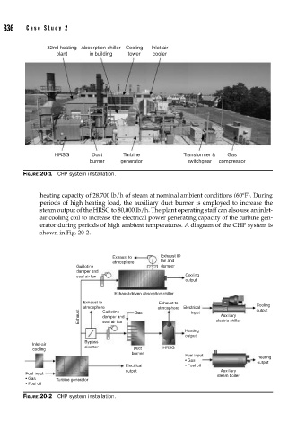
82nd heating Absorption chiller Cooling Inlet air
plant in building tower cooler
HRSG Duct Turbine Transformer & Gas
burner generator switchgear compressor
FIGURE 20-1 CHP system installation.
heating capacity of 28,700 lb/h of steam at nominal ambient conditions (60°F). During
periods of high heating load, the auxiliary duct burner is employed to increase the
steam output of the HRSG to 80,000 lb/h. The plant operating staff can also use an inlet-
air cooling coil to increase the electrical power generating capacity of the turbine gen-
erator during periods of high ambient temperatures. A diagram of the CHP system is
shown in Fig. 20-2.
Exhaust to Exhaust ID
atmosphere fan and
Guillotine damper
damper and
seal air fan Cooling
output
Exhaust-driven absorption chiller
Exhaust to Exhaust to
atmosphere Guillotine atmosphere Electrical Cooling
output
Exhaust damper and Gas input electric chiller
Auxiliary
seal air fan
Heating
output
Bypass
Inlet-air
cooling diverter Duct HRSG
burner
Fuel input
Heating
• Gas output
Electrical • Fuel oil
output Auxiliary
Fuel input
steam boiler
• Gas Turbine generator
• Fuel oil
FIGURE 20-2 CHP system installation.