
Page 416 - Sustainable On-Site CHP Systems Design, Construction, and Operations
P. 416
Eco-Footprint of On-Site CHP versus EPGS Systems 389
directly to a modified two-stage direct gas-fired LiBr-water absorption chiller configu-
ration have already been demonstrated (Berry et al. 2004 and 2005; Meckler and Hyman
2005; Pathakji et al. 2005).
Achieving the earlier described synergies within on-site CHP systems, however,
requires thinking “out of the proverbial box” to identify similar converging opportuni-
ties by enhancing gas turbine engine performance at lower prime energy and overall
capital cost. Close-coupled turbine inlet cooling, supplied from two- and/or single-stage
steam (or hot water) absorption chillers, benefits enhanced turbine power performance.
Description of Compared Systems
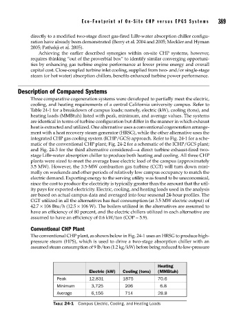
Three comparative cogeneration systems were developed to partially meet the electric,
cooling, and heating requirements of a central California university campus. Refer to
Table 24-1 for a breakdown of campus loads; namely, electric (kW), cooling (tons), and
heating loads (MMBtuh) listed with peak, minimum, and average values. The systems
are identical in terms of turbine configuration but differ in the manner in which exhaust
heat is extracted and utilized. One alternative uses a conventional cogeneration arrange-
ment with a heat recovery steam generator (HRSG), while the other alternative uses the
integrated CHP gas cooling system (ICHP/GCS) approach. Refer to Fig. 24-1 for a sche-
matic of the conventional CHP plant; Fig. 24-2 for a schematic of the ICHP/GCS plant;
and Fig. 24-3 for the third alternative considered—a direct turbine exhaust-fired two-
stage LiBr-water absorption chiller to produce both heating and cooling. All three CHP
plants were sized to meet the average base electric load of the campus (approximately
3.5 MW). However, the 3.5-MW combustion gas turbine (CGT) will turn down mini-
mally on weekends and other periods of relatively low campus occupancy to match the
electric demand. Exporting energy to the serving utility was found to be uneconomical,
since the cost to produce the electricity is typically greater than the amount that the util-
ity pays for exported electricity. Electric, cooling, and heating loads used in the analysis
are based on actual campus data and averaged into four seasonal 24-hour profiles. The
CGT utilized in all the alternatives has fuel consumption (at 3.5 MW electric output) of
42.7 × 10⁶ Btu/h (12.5 × 10⁶ W). The boilers utilized in the alternatives are assumed to
have an efficiency of 80 percent, and the electric chillers utilized in each alternative are
assumed to have an efficiency of 0.6 kW/ton (COP = 5.9).
Conventional CHP Plant
The conventional CHP plant, as shown below in Fig. 24-1 uses an HRSG to produce high-
pressure steam (HPS), which is used to drive a two-stage absorption chiller with an
assumed steam consumption of 9 lb/ton (1.2 kg/kW) before being reduced to low-pressure
Heating
Electric (kW) Cooling (tons) (MMBtuh)
Peak 12,831 1875 70.6
Minimum 3,725 206 6.8
Average 6,156 714 28.8
TABLE 24-1 Campus Electric, Cooling, and Heating Loads