
Page 89 - Sustainable On-Site CHP Systems Design, Construction, and Operations
P. 89
Thermal Design for CHP 67
125
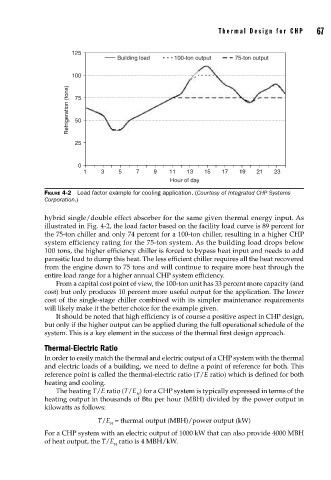
Building load 100-ton output 75-ton output
100
Refrigeration (tons) 75
50
25
0
1 3 5 7 9 11 13 15 17 19 21 23
Hour of day
FIGURE 4-2 Load factor example for cooling application. (Courtesy of Integrated CHP Systems
Corporation.)
hybrid single/double effect absorber for the same given thermal energy input. As
illustrated in Fig. 4-2, the load factor based on the facility load curve is 89 percent for
the 75-ton chiller and only 74 percent for a 100-ton chiller, resulting in a higher CHP
system efficiency rating for the 75-ton system. As the building load drops below
100 tons, the higher efficiency chiller is forced to bypass heat input and needs to add
parasitic load to dump this heat. The less efficient chiller requires all the heat recovered
from the engine down to 75 tons and will continue to require more heat through the
entire load range for a higher annual CHP system efficiency.
From a capital cost point of view, the 100-ton unit has 33 percent more capacity (and
cost) but only produces 10 percent more useful output for the application. The lower
cost of the single-stage chiller combined with its simpler maintenance requirements
will likely make it the better choice for the example given.
It should be noted that high efficiency is of course a positive aspect in CHP design,
but only if the higher output can be applied during the full operational schedule of the
system. This is a key element in the success of the thermal first design approach.
Thermal-Electric Ratio
In order to easily match the thermal and electric output of a CHP system with the thermal
and electric loads of a building, we need to define a point of reference for both. This
reference point is called the thermal-electric ratio (T/E ratio) which is defined for both
heating and cooling.
The heating T/E ratio (T/E ) for a CHP system is typically expressed in terms of the
H
heating output in thousands of Btu per hour (MBH) divided by the power output in
kilowatts as follows:
T/E = thermal output (MBH)/power output (kW)
H
For a CHP system with an electric output of 1000 kW that can also provide 4000 MBH
of heat output, the T/E ratio is 4 MBH/kW.
H