
Page 92 - Sustainable On-Site CHP Systems Design, Construction, and Operations
P. 92
70 CHP B a s i c s
20.000
LT HW HT HW 15-psig steam
18.000
16.000
Heat recovered (MBH) 12.000
14.000
10.000
8.000
6.000
4.000
2.000
0.000
75 255 375 450 600 750 769 770 980 1100 1100 1200 1250 1400 1750 2055 2615 3480 5238
Engine output (kW)
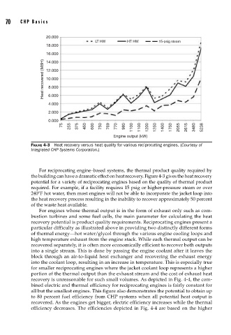
FIGURE 4-3 Heat recovery versus heat quality for various reciprocating engines. (Courtesy of
Integrated CHP Systems Corporation.)
For reciprocating engine–based systems, the thermal product quality required by
the building can have a dramatic effect on heat recovery. Figure 4-3 gives the heat recovery
potential for a variety of reciprocating engines based on the quality of thermal product
required. For example, if a facility requires 15 psig or higher-pressure steam or over
240°F hot water, then most engines will not be able to incorporate the jacket loop into
the heat recovery process resulting in the inability to recover approximately 50 percent
of the waste heat available.
For engines whose thermal output is in the form of exhaust only such as com-
bustion turbines and some fuel cells, the main parameter for calculating the heat
recovery potential is product quality requirements. Reciprocating engines present a
particular difficulty as illustrated above in providing two distinctly different forms
of thermal energy—hot water/glycol through the various engine cooling loops and
high temperature exhaust from the engine stack. While each thermal output can be
recovered separately, it is often more economically efficient to recover both outputs
into a single stream. This is done by passing the engine coolant after it leaves the
block through an air-to-liquid heat exchanger and recovering the exhaust energy
into the coolant loop, resulting in an increase in temperature. This is especially true
for smaller reciprocating engines where the jacket coolant loop represents a higher
portion of the thermal output than the exhaust stream and the cost of exhaust heat
recovery is unreasonable for such small volumes. As depicted in Fig. 4-4, the com-
bined electric and thermal efficiency for reciprocating engines is fairly constant for
all but the smallest engines. This figure also demonstrates the potential to obtain up
to 80 percent fuel efficiency from CHP systems when all potential heat output is
recovered. As the engines get bigger, electric efficiency increases while the thermal
efficiency decreases. The efficiencies depicted in Fig. 4-4 are based on the higher