
Page 93 - Sustainable On-Site CHP Systems Design, Construction, and Operations
P. 93
Thermal Design for CHP 71
100
Total CHP efficiency Thermal efficiency Electric efficiency
90
80
70
Efficiency (%) 50
60
40
30
20
10
0
75 255 260 375 375 450 600 750 769 770 980 1100 1100 1200 1250 1400 1750 2055 2615 3480 5238
Engine size (kW)
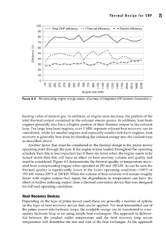
FIGURE 4-4 Reciprocating engine energy output. (Courtesy of Integrated CHP Systems Corporation.)
heating value of natural gas. In addition, as engine sizes increase, the portion of the
total thermal output contained in the exhaust stream grows. In addition, lean burn
engines generally also have a higher portion of their thermal output in the exhaust
loop. For large lean burn engines, over 1 MW, separate exhaust heat recovery can be
considered, while for smaller engines and especially smaller rich burn engines, heat
recovery is generally best done by blending the exhaust energy into the coolant loop
as described above.
Another factor that must be considered in the thermal design is the prime mover
operating point through the year. If the engine is base loaded throughout the operating
schedule then this is less important but if there are times when the engine needs to be
turned down then this will have an effect on heat recovery volume and quality and
must be considered. Figure 4-5 demonstrates the thermal quality or temperature recov-
ered from a reciprocating engine when operated at 250 and 150 kW. As can be seen the
thermal quality is significantly lower at the lower operating condition—198°F at
150 kW versus 205°F at 250 kW. While the volume of heat recovery will remain roughly
linear with engine output/fuel input, the degradation in temperature can have the
effect of further reducing output from a thermal conversion device that was designed
for full load operating conditions.
Heat Recovery Devices
Depending on the type of prime mover used, there are generally a number of options
on the type of heat recovery device that can be applied. For heat transmitted out of
the prime mover into hydronic loops, the available energy can be transferred to a sec-
ondary hydronic loop or air using simple heat exchangers. The approach or differen-
tial between the product outlet temperature and the heat recovery loop return
temperature will determine the size and cost of the heat exchanger. As the approach