
Page 97 - Sustainable On-Site CHP Systems Design, Construction, and Operations
P. 97
Thermal Design for CHP 75
concentrations, while single-stage absorbers have somewhat better capabilities to use
low condenser water temperatures due to the lower solution concentrations found in
these chillers.
The choice to use hot water or steam to fire the absorber is based on the site’s need
to have hot water or steam available for other purposes and generally does not impact
the chiller cost, efficiency, or operation. In applications that generate high-pressure
steam (greater than 100 psig) or high temperature hot water (greater than 300°F), the
higher efficient two-stage absorbers are generally preferred. It should be noted,
however, that the choice of efficiency should be subject to the availability of load as
mentioned in the earlier section on thermal design. For applications that require high-
pressure steam but do not have high cooling loads, then the single-effect chiller can
provide the cooling required at a significantly lower capital cost than two-stage absorp-
tion units.
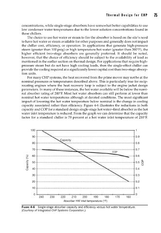
For many CHP systems, the heat recovered from the prime mover may not be at the
nominal pressures or temperatures described above. This is particularly true for recip-
rocating engines where the heat recovery loop is subject to the engine jacket design
parameters. In many of these instances, the hot water available will be below the nomi-
nal absorber rating of 240°F. Most hot water absorbers can still perform at lower than
nominal hot water temperatures although at derated conditions. The most significant
impact of lowering the hot water temperature below nominal is the change in cooling
capacity associated rather than efficiency. Figure 4-6 illustrates the reductions in both
capacity and COP for a standard design single-stage hot water–fired absorber as the hot
water inlet temperature is reduced. From the graph we can determine that the capacity
factor for a standard chiller is 70 percent at a hot water inlet temperature of 210°F.
100 1
90 0.9
Capacity
80 0.8
70 0.7
COP 0.6
60
Capacity (%) 50 0.5 COP
0.4
40
30 0.3
20 0.2
10 0.1
0 0
240 230 220 210 200 190 180 170 160
Absorber HW inlet temperature (°F)
FIGURE 4-6 Single-stage absorber capacity and effi ciency versus hot water temperature.
(Courtesy of Integrated CHP Systems Corporation.)