
Page 102 - Sustainable On-Site CHP Systems Design, Construction, and Operations
P. 102
80 CHP B a s i c s
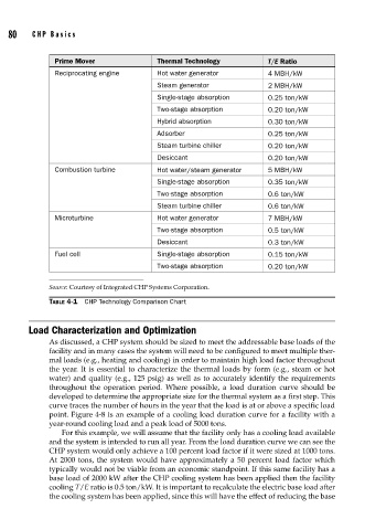
Prime Mover Thermal Technology T/E Ratio
Reciprocating engine Hot water generator 4 MBH/kW
Steam generator 2 MBH/kW
Single-stage absorption 0.25 ton/kW
Two-stage absorption 0.20 ton/kW
Hybrid absorption 0.30 ton/kW
Adsorber 0.25 ton/kW
Steam turbine chiller 0.20 ton/kW
Desiccant 0.20 ton/kW
Combustion turbine Hot water/steam generator 5 MBH/kW
Single-stage absorption 0.35 ton/kW
Two-stage absorption 0.6 ton/kW
Steam turbine chiller 0.6 ton/kW
Microturbine Hot water generator 7 MBH/kW
Two-stage absorption 0.5 ton/kW
Desiccant 0.3 ton/kW
Fuel cell Single-stage absorption 0.15 ton/kW
Two-stage absorption 0.20 ton/kW
Source: Courtesy of Integrated CHP Systems Corporation.
TABLE 4-1 CHP Technology Comparison Chart
Load Characterization and Optimization
As discussed, a CHP system should be sized to meet the addressable base loads of the
facility and in many cases the system will need to be configured to meet multiple ther-
mal loads (e.g., heating and cooling) in order to maintain high load factor throughout
the year. It is essential to characterize the thermal loads by form (e.g., steam or hot
water) and quality (e.g., 125 psig) as well as to accurately identify the requirements
throughout the operation period. Where possible, a load duration curve should be
developed to determine the appropriate size for the thermal system as a first step. This
curve traces the number of hours in the year that the load is at or above a specific load
point. Figure 4-8 is an example of a cooling load duration curve for a facility with a
year-round cooling load and a peak load of 5000 tons.
For this example, we will assume that the facility only has a cooling load available
and the system is intended to run all year. From the load duration curve we can see the
CHP system would only achieve a 100 percent load factor if it were sized at 1000 tons.
At 2000 tons, the system would have approximately a 50 percent load factor which
typically would not be viable from an economic standpoint. If this same facility has a
base load of 2000 kW after the CHP cooling system has been applied then the facility
cooling T/E ratio is 0.5 ton/kW. It is important to recalculate the electric base load after
the cooling system has been applied, since this will have the effect of reducing the base