
Page 252 -
P. 252
chaPter 8 • analyzing systems Using Data Dictionaries 219
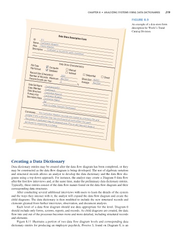
Figure 8.9
An example of a data store form
description for World’s Trend
Catalog Division.
ID D 1 Data Store Description Form
Name Customer Master
Alias Client Master
Description Contains a record for each customer.
File Type Data Store Characteristics
Computer
File Format
Manual
Database
Indexed
Record Size (Characters):
200 Sequential
Direct
Number of Records: Maximum 45,000
Block Size: 4000
Percent Growth per Year:
6 Average: 42,000
%
Data Set Name
Customer.MST
Copy Member
Custmast
Data Structure
Customer Record
Primary Key
Customer Number
Secondary Keys Customer Name
Zip
Year-to-Date Amount Purchased
Comments The Customer Master records are copied to a history file and
purged if the customer has not purchased an item within the past
purchase by requesting a catalog.
five years. A customer may be retained even if he or she has not made a
Creating a Data Dictionary
Data dictionary entries may be created after the data flow diagram has been completed, or they
may be constructed as the data flow diagram is being developed. The use of algebraic notation
and structural records allows an analyst to develop the data dictionary and the data flow dia-
grams using a top-down approach. For instance, the analyst may create a Diagram 0 data flow
after the first few interviews and, at the same time, make the preliminary data dictionary entries.
Typically, these entries consist of the data flow names found on the data flow diagram and their
corresponding data structures.
After conducting several additional interviews with users to learn the details of the system
and the ways they interact with it, the analyst will expand the data flow diagram and create the
child diagrams. The data dictionary is then modified to include the new structural records and
elements gleaned from further interviews, observation, and document analysis.
Each level of a data flow diagram should use data appropriate for the level. Diagram 0
should include only forms, screens, reports, and records. As child diagrams are created, the data
flow into and out of the processes becomes more and more detailed, including structural records
and elements.
Figure 8.11 illustrates a portion of two data flow diagram levels and corresponding data
dictionary entries for producing an employee paycheck. Process 5, found on Diagram 0, is an